3. Getting Started
- For a better usability, the product comes up with a start page, where the user can choose what he wants to do:
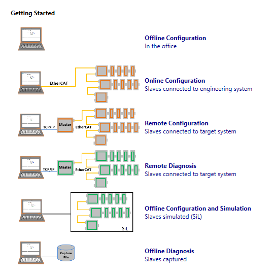
3.1. Offline Configuration
This mode is for configuring the EtherCAT network in the office by manually adding slaves to the network.
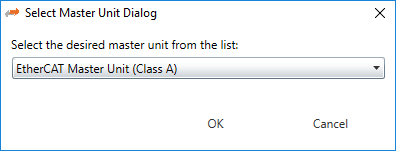
- If the user clicks on this link he will see first the for choosing the desired master unit (at the moment he can choose between Class A and Class B master):
- Afterwards he will see the , where he can configure his EtherCAT network:
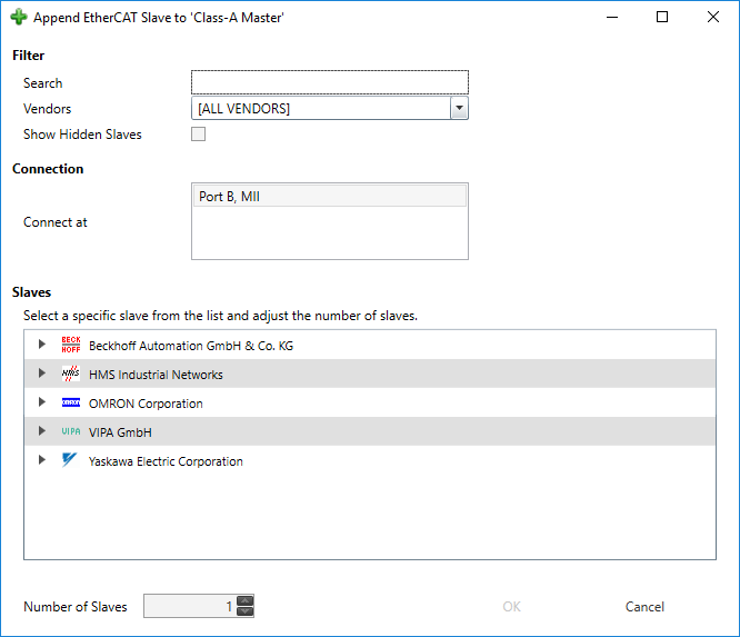
If you can not find your slave or if you want to use your own ESI file, you can edit this list by using the ESI-Manager. After configuring the network you can select the node and use the Export ENI button for generating an ENI file.
3.2. Online Configuration
This mode can be used if slaves are connected to the Engineering System by scanning the EtherCAT network configuration.
- If user clicks on this link he will see first the for choosing the desired master unit (at the moment he can choose between Class A and Class B master):
-
- Afterwards he will see the , where he can choose the network adapter which is connected to the control system:
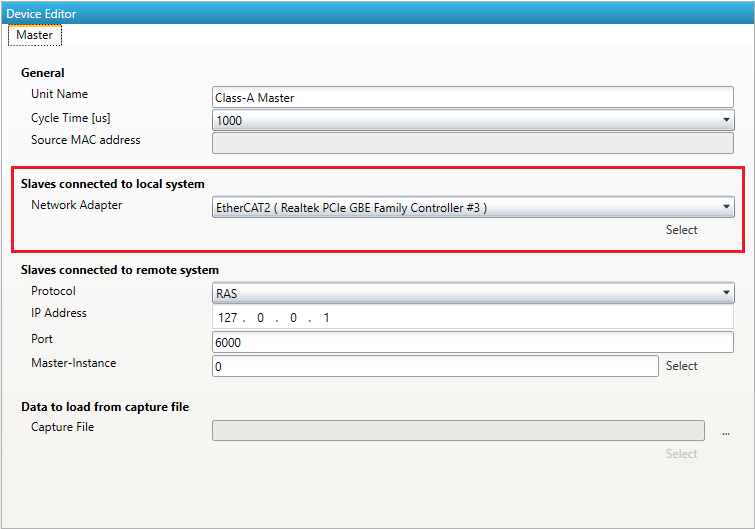
After selecting the network adapter, the EC-Engineer scans the control system and adds the network configuration to the project explorer. Here the user can adjust the configuration or use the Export ENI button for
generating directly an ENI file.
3.3. Remote Configuration
This mode can be used if slaves are connected to the control system. Means user can connect via TCP/IP to the control system if EC-Master RAS (remote access service) server is running and scan the EtherCAT network configuration.
- If user clicks on this link he will see first the for choosing the desired master unit (at the moment he can choose between Class A and Class B master):
-
- Afterwards he will see the , where he can enter the IP address of the remote system (and if necessary change the port and the master-instance, but normally this should not be necessary):
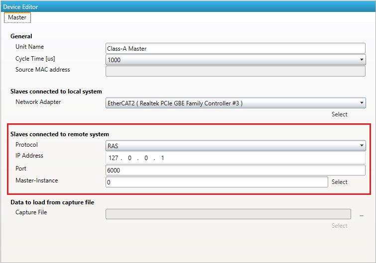
After entering the IP address, a click to Select tells the EC-Engineer to connect to and scan the remote system. The EC-Engineer adds all Slaves of the network configuration to the project explorer. Here the
user can adjust the configuration or use the Export ENI button for generating directly an ENI file.
3.4. Remote Diagnosis
This mode should be used if the EC-Master is already running on the control system and the user wants to take a look into the “health” of the EtherCAT system.
- If user clicks on this link he will see first the for choosing the desired master unit (at the moment he can choose between Class A and Class B master):
-
- Afterwards he will see the , where he can enter the IP address of the remote system (and if necessary change the port and the master-instance, but normally this should not be necessary):
-
After entering the IP address, a click to Select switches the EC-Engineer into Diagnosis Mode. There the user sees the “health” of his EtherCAT system.
3.5. Offline Configuration and Simulation
This mode is for configuring the EtherCAT network in the office by manually adding slaves to the network.
- If the user clicks on this link he will see first the for choosing the desired master unit (at the moment he can choose between Class A and Class B master):
-
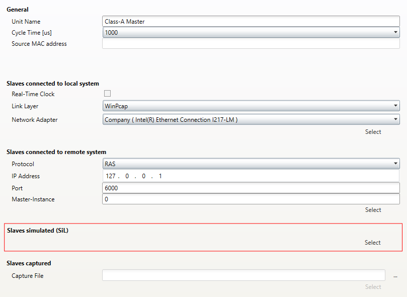
- Then the user have to select the simulator:
- Afterwards he will see the , where he can configure his EtherCAT network:
-
If you can not find your slave or if you want to use your own ESI file, you can edit this list by using the ESI-Manager.
After configuring the network you can select the network node and use the Export ENI button for generating an ENI file or switch to diagnosis mode and simulate the network.
3.6. Offline Diagnosis
This mode should be used if the user wants to analyse a previously created capture file. This can be done offline, which means that the “real system” no not necessary.
- If user clicks on this link he will see first the for choosing the desired master unit (at the moment he can choose between Class A and Class B master):
-
- Afterwards he will see the , where he can enter the path to the capture, which contains one or more previously taken snapshots:
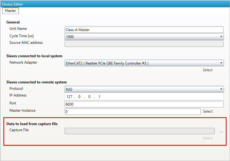
After choosing the path to the capture file, a click to Select switches the EC-Engineer into Diagnosis Mode. Now, the user can analyse the previously taken snapshots of a EtherCAT system.