8. Additional Tools
8.1. ESI-Manager
ESI-Manager can be found through the main menu File -> ESI-Manager.
- This dialog helps the user to administrate his
ESIandSCIfiles. Here, he can add/delete/exportESIandSCIfiles. 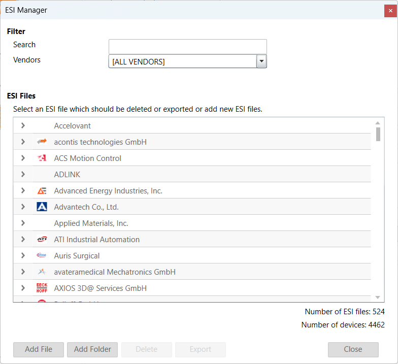
8.2. EMI-Manager
EMI-Manager can be found through the main menu File -> EMI-Manager.
- This dialog helps the user to administrate his EtherCAT MainDevice Information (
EMI) files. 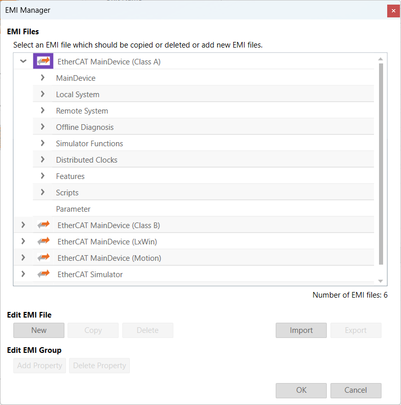
EMI files, are files which are specify the MainDevice features. Means that options and dialogs can be restricted to those features which are supported by the control system, e.g. available cycle times, support of scan for MDP modules or DC synchronization.
8.2.1. Administration
This dialog helps the user to administrate his EtherCAT MainDevice Information (EMI) files.
- By default EC-Engineer has two files included (read-only):
EtherCATMaster_ClassA.emi:EMItemplate which is prepared for configuring a “Class A” MainDeviceEtherCATMaster_ClassB.emi:EMItemplate which is prepared for configuring a “Class B” MainDevice
If the user wants to customize EC-Engineer, he can create a new EMI file with defaults, copy an existing EMI template or import an EMI file.
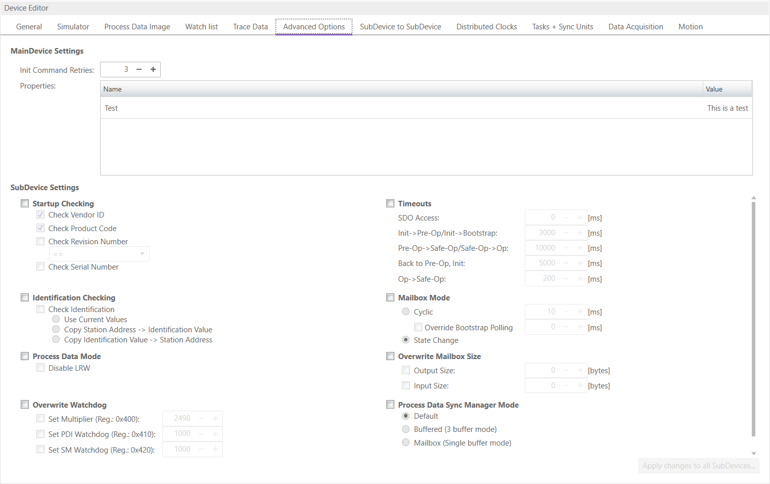
If he wants to add new properties to a group, he can add this only to the group “Parameters”. This group is by default empty, but if user has added some properties, he will see the list of properties on tab “Advanced Options” of the MainDevice, where the values can be modified.
8.2.2. Supported Entries
The following EMI entries are supported:
- MainDevice Group
- Display Group:
Shows or hides group
- Lock Group:
Locks or unlocks group
- Name of MainDevice:
Default MainDevice name
- Show name of MainDevice:
Enable if user should be able to view and change the name of the MainDevice
- Lock name of MainDevice:
Enable if user should not be able to change the name of the MainDevice
- Cycle Time:
Default Cycle Time
- Show Cycle Time:
Enable if user should be able to view and change the Cycle Time
- Lock Cycle Time:
Enable if user should not be able to change the Cycle Time
- List values of Cycle Time:
Enter possible values of Cycle Time
- Frequency:
Default Frequency
- Show Frequency:
Enable if user should be able to view and change the Frequency
- Lock Frequency:
Enable if user should not be able to change the Frequency
- List values of Frequency:
Enter possible values of Frequency
- Cycle Time Mode:
Enter Cycle Time Mode (0 = Cycle Time, 1 = Frequency)
- Init Command Retries:
Init Command Retries
- Maximal SubDevice Count:
Enter maximal count of SubDevices which are allowed to configure (0 = use default limit of MainDevice)
- SubDevice Start Address:
Enter default start address for all SubDevices
- Scan for MDP SubDevices:
Enable for activating MDP-Scan if it is supported from SubDevice
- PDO Upload:
Enable for activating PDO upload during scan if it is supported from SubDevice
- Byte-Align Process Data Image:
Enable if process data image should be byte aligned and not as small as possible
- Edit Complete Variable Name:
Enable if user should be able to edit the complete variable name
- Process Image Layout:
Enter process image layout features (0 = default, 0x1 = with protocol data, 0x2 = with VLAN tag, 0x4 = without frame alignment, 0x8 = alphabetic port order, 0x10 = Compatibility to
ENIspec V1.0.0, 0x20 = Moves AL Status command to the end, 0x40 = Disable command splitting, 0x80 = Compatibility toENIspec V1.0.1)- Output Port Vendor Id:
Enter output port vendor id of the MainDevice (0 = All Vendors, 1..n = Specific Vendor)
- Word-Aligned EtherCAT Datagrams:
Enable if EtherCAT datagrams should be word aligned
- Cyclic Frame Layout:
Enter cyclic frame layout mode (0 = default, 1 = single logical command per frame)
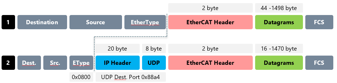
- Ethernet Type UDP:
- Remove DC NOP Command:
Does not include NOP Command in
ENI- Cable Redundancy:
Sets disable LRW for all SubDevices to use cable redundancy and enables an opportunity to select a second adapter and link-layer
- Junction Redundancy:
Allows to user to scan also with connected junction redundancy
- Local System

- Display Group:
Shows or hides group
- Lock Group:
Locks or unlocks group
- Network Adapter:
Enter index of Network Adapter in the Network Adapter List
- Show Network Adapter:
Enable if user should be able to view and change the Network Adapter
- Lock Network Adapter:
Enable if user should not be able to change the Network Adapter
- DCM on:
EC-Engineer deactivated DCM on default. Enable if it should be turned off
- Remote System

- Display Group:
Shows or hides group
- Lock Group:
Locks or unlocks group
- Protocol:
Select protocol for Remote System
- Show Protocol:
Enable if user should be able to view and change the protocol
- Lock Protocol:
Enable if user should be not able to change the protocol
- IP Address:
Enter IP Address for Remote System
- Show IP Address:
Enable if user should be able to view and change the IP Address
- Lock IP Address:
Enable if user should be not able to change the IP Address
- Port:
Enter Port for Remote System
- Show Port:
Enable if user should be able to view and change the Port”
- Lock Port:
Enable if user should be not able to change the Port
- MainDevice-Instance:
Enter MainDevice-Instance number
- Show MainDevice-Instance:
Enable if user should be able to view and change the MainDevice-Instance
- Lock MainDevice-Instance:
Enable if user should be not able to change the MainDevice-Instance
- Offline Diagnosis

- Display Group:
Shows or hides group
- Lock Group:
Locks or unlocks group
- Simulator Functions
- Display Group:
Shows or hides group
- Lock Group:
Locks or unlocks group
- Distributed Clocks
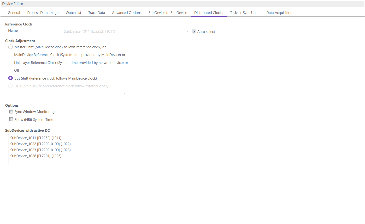
- Display Group:
Shows or hides group
- Clock Adjustment:
Enter clock adjustment value (0 = default, 1 = MainDevice Shift, 2 = Bus Shift
- Lock Clock Adjustment:
Enable if user should not be able to change clock adjustment
- Show Clock Adjustment:
Enable if clock adjustment should be visible
- Continuous Propagation Compensation:
Enter default value of Continuous Propagation Compensation
- Show Continuous Propagation Compensation:
Enable if user should be able to change value of Continuous Propagation Compensation
- Sync Window Monitoring:
Enter default value of Sync Window Monitoring
- Show External Mode:
Enable if user should be able to use an external sync device as reference clock
- System Time 64 Bit:
Enter default value of System Time 64 Bit
- Features
- AoE:
Enable if MainDevice supports AoE
- EoE:
Enable if MainDevice supports EoE
- FoE:
Enable if MainDevice supports FoE
- SoE:
Enable if MainDevice supports SoE
- VoE:
Enable if MainDevice supports VoE
- Export Variables:
Enable if user should be able to export variables
- Show Enable Column:
Shows column for enable variables on
XMLexport- Generate SubDevice Name with Type:
Enable if type of SubDevice should be added to SubDevice names on generating
ENIfile- Lock Variables:
Locks or unlocks variables for editing in diagnosis mode
- Show Variable Chart:
Enable if user should be able to view the chart of a variable
- Show Variable Comments:
Enable if user should be able to view and edit the comments of a variable
- Allow E-Bus as HC Head:
Enable if Ebus shall be allowed as HC Head
ENIDeployment:yes: something is done with
ENIafter export, no: nothing done ask: you will be ask to deploy- Deployment Mode:
0: copy to path, 1: execute batch at path
- Deployment Path:
Path to copy
ENIor to batch for execution- Hot Connect:
Enable if MainDevice supports hot connect
- Scripts
- Display Group:
Shows or hides the Scripts Tab
- P1:
- Scan Start Script 1:
First script executed before scanning
- Scan Start Script 2:
Second script executed before scanning
- Scan Stop Script 3:
First script executed after scanning
- Scan Stop Script 4:
Second script executed after scanning
- P2:
- Diag Start Script 1:
First script executed before switch to diag
- Diag Start Script 2:
Second script executed before switch to diag
- Diag Stop Script 3:
First script executed before switching to config
- Diag Stop Script 4:
Second script executed before switching to config
- Parameters
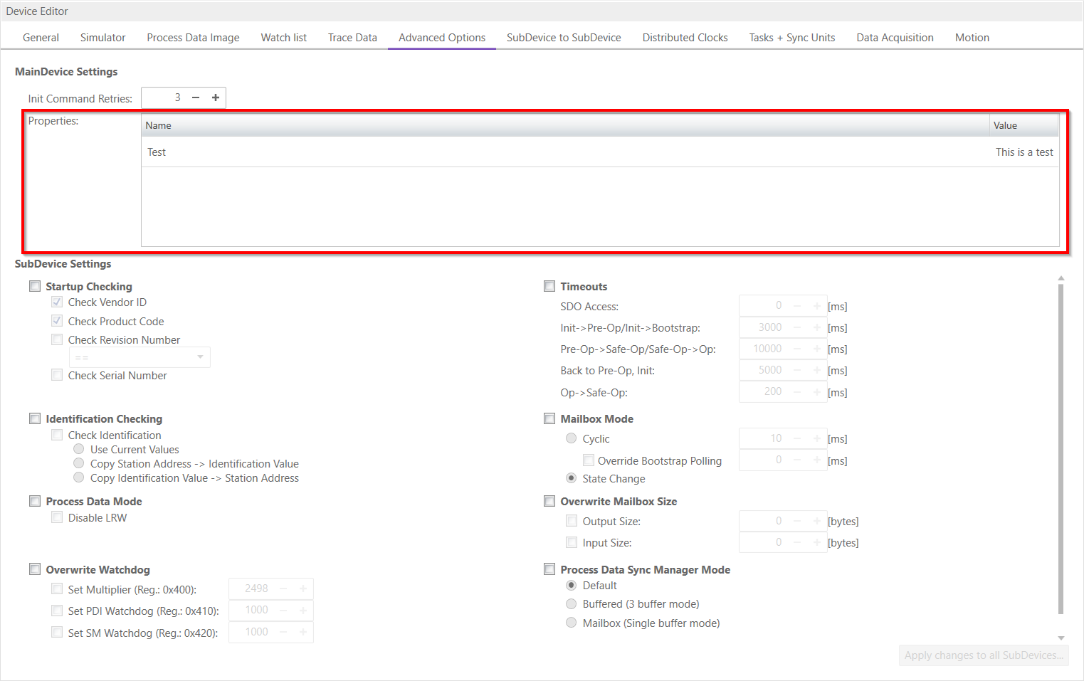
User defined properties, which will be written into
ENIfile and can be interpreted by the application inside EC-Master.
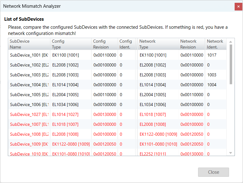
8.3. Network Mismatch Analyzer
- If you have a network mismatch in your EtherCAT network it is not so easy to find the problem. For this you have the Network Mismatch Analyzer. You find it in the network main menu. If you see here some “red” entries, means that this is the start point of your network mismatch:
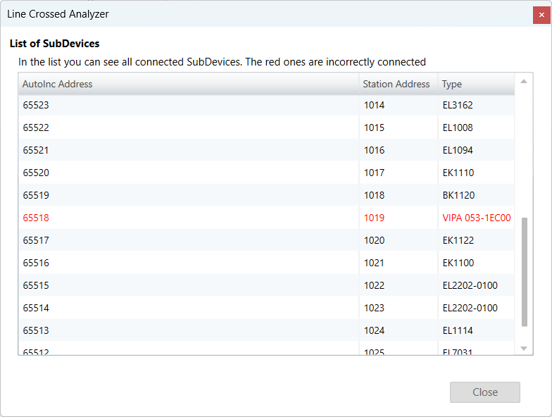
8.4. Line Crossed Analyzer
- If you have connected a line to a wrong port, you can see in the Line Crossed Analyzer which SubDevice is incorrectly connected. The wron entries will be red:
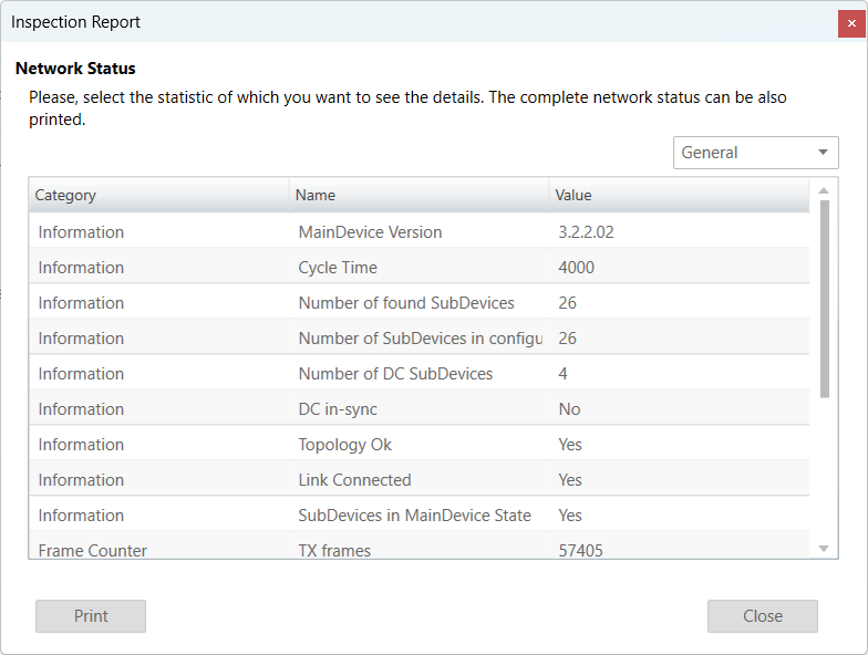
8.5. Inspection Report
- If you want to print or show a report about the actual session, it is possible with the inspection report. I shows a lot of different data about the network communication. It is also possible to print a PDF.
8.6. EoE Endpoint Configuration
If you want to use EoE SubDevices with your local MainDevice, you can activate the EoE Endpoint.
Note
This feature is only available if the package “Tap-Windows” from OpenVPN is installed: http://openvpn.net/index.php/download/community-downloads.html
- If this package is installed, you will see the following dialog:
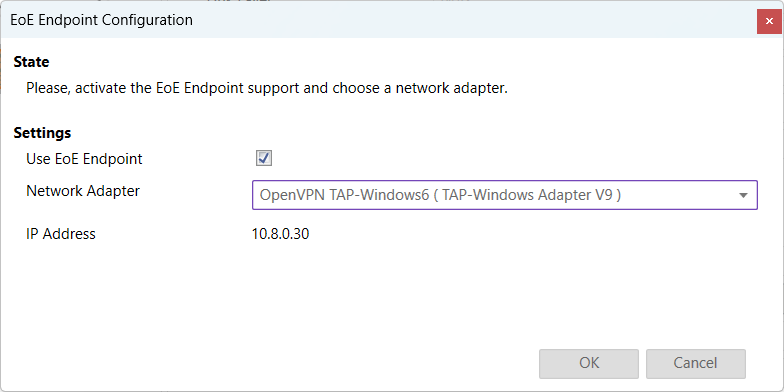
- Settings
- Use EoE Endpoint:
Activate EoE Endpoint support for the selected device
- Network Adapter:
List of installed network adapters (TAP)
- IP Address:
IP Address of the selected network adapter
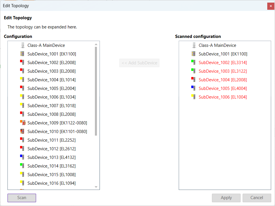
8.7. Edit Topology
- Disconnect:
Disconnets the selected port
- Connect:
Connects the selected SubDevice in the not connect SubDevices list, with the selected port in the configuration
- Up:
Moves the SubDevice up in the configuration
- Down:
Moves the SubDevice down in the configuration
- Scan:
Scans the network. The network is shown by the scanned configuration. It is possible to add SubDevice to the configuration with “Add SubDevice”.
- Apply:
The configuration will be applied to the EC-Engineer (only possible if all SubDevices are connected)
8.8. Self Test Scan
To perform a Self Test Scan, a MainDevice and a target system must be selected.
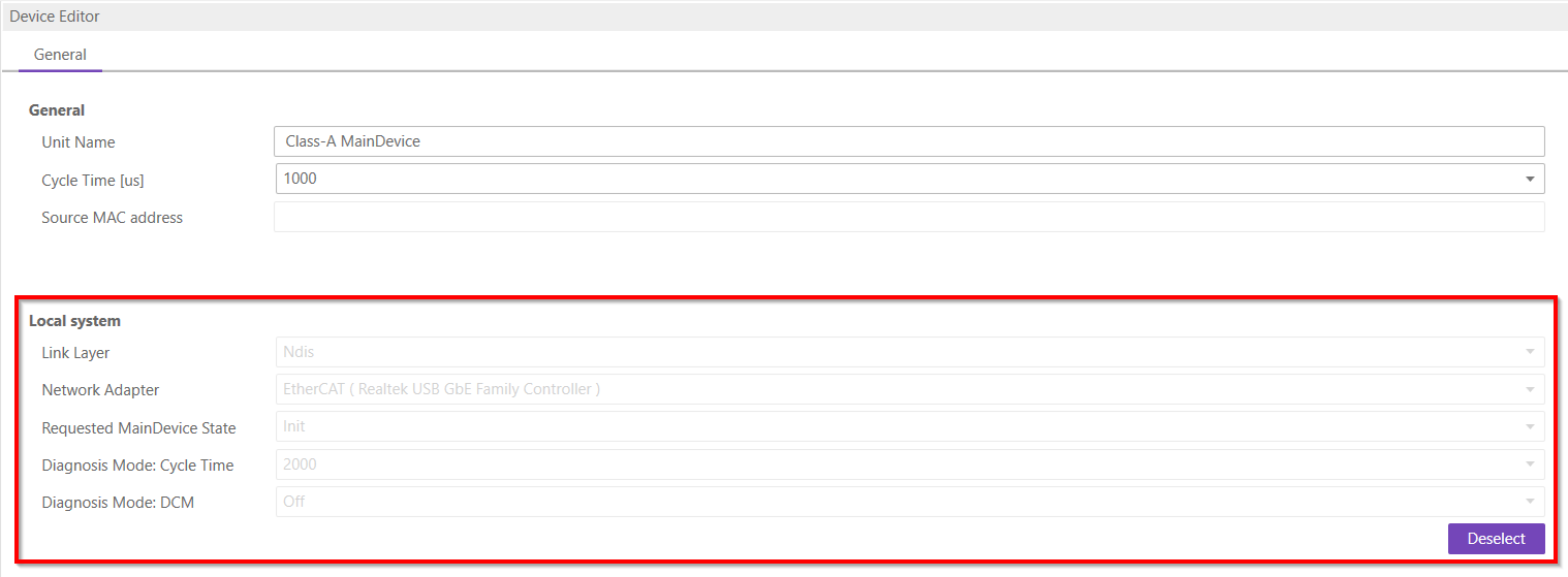
The settings for the Self Test Scan can be found on the expert tab in the settings dialog, see Expert.
After the Self Test Scan is successful, we get the following logs from the message panel.
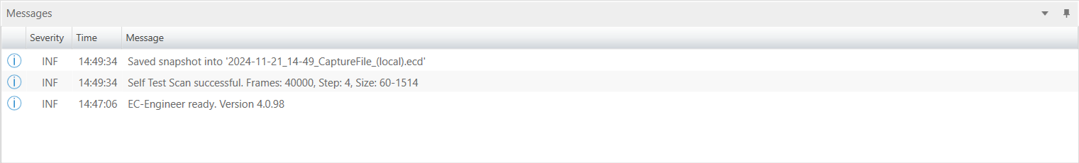
A capture file is produce after the scan and it is saved to diagnose the results. The file is saved in the path given in the capture file settings.
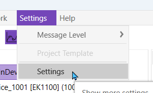
8.9. Settings
Can be found inside the settings menu bar.
8.9.1. General
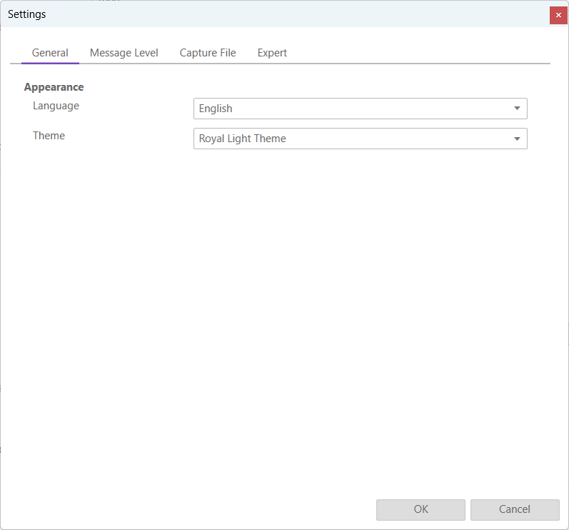
- Appearance
- Language:
Changes the current language
- Theme:
Changes the current theme
8.9.2. Message Level
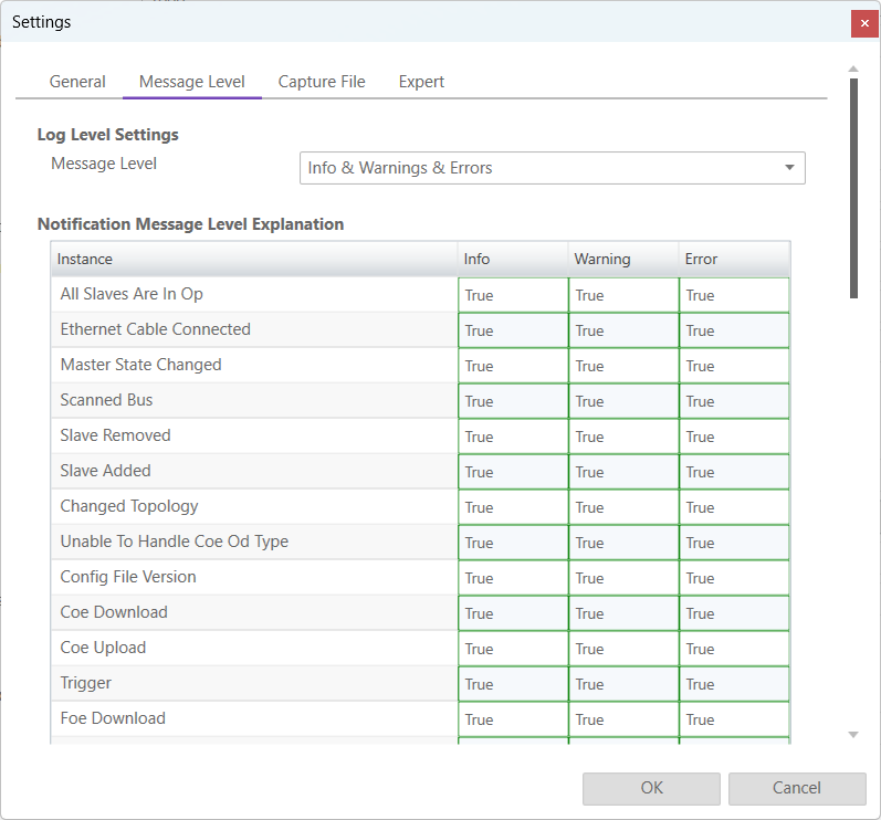
In this tab the log level of the message panel can be changed.
- Log Level Settings
- Message Level:
Changes what messages are displayed on the message panel
- Explanation
We can see what messages are displayed depending on the selected message level (true it is displayed, false it is not displayed)
8.9.3. Capture File
A capture file could be helpful, if a very large system is given or the system is not always available. In that case the user can connect to their system, save one or more snapshots into a capture file and analyse the created capture file later.
Another use case is, that their system from time to time some problems. In that case the user can activate the automatic mode and create the snapshots at specific intervals or based on specific MainDevice notifications.
- At the moment there are the following options:
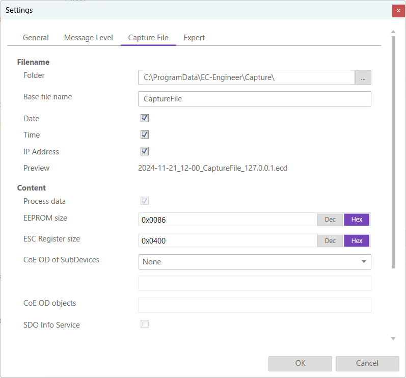
- Filename
- Folder:
Path, where the capture files should be saved
- Base file name:
Base file name of the generated capture file name
- Date:
Activate, to add the date to the generated capture file name
- Time:
Activate, to add the time to the generated capture file name
- IP Address:
Activate, to add the IP address to the generated capture file name
- Preview:
Shows a preview of the generated capture file name
- Content
- Process data:
Activate to add process data to the capture file (read-only)
- EEPROM size:
Enter size of the EEPROM (0x86 = default, 0 = no EEPROM)
- ESC Register size:
Enter size of the ESC Registers (0x400 = default, 0 = no ESC register)
- CoE OD of SubDevices:
- Select the SubDevices of which the CoE OD information will be captured
- None:
CoE OD will be not captured
- All:
CoE OD will be captured of all SubDevices
- User defined:
CoE OD will be captured of the defined SubDevices by physical address (e.g. 1001-1003; 1005)
- CoE OD objects:
Enter index of specific objects or all objects will be collected (e.g. 0x1018; 0x7000-0x7FFF)
- SDO Info Service:
Activate to use the SDO Info Service for loading the CoE Object Dictionary instead of readying the information from the
ESIfile.
- Automatic Mode
- Interval (min):
Time to wait until next snapshot will be taken
- Maximum Snapshots:
Enter count of maximum snapshots
- Notifications:
- Select the notifications, which will trigger a snapshot. The following notifications are availabe (for more information about notifications please refer the manual of EC-Master):
STATECHANGED
ETH_LINK_CONNECTED
ETH_LINK_NOT_CONNECTED
SLAVE_STATECHANGED
SLAVE_PRESENCE
SLAVE_INITCMD_RESPONSE_ERROR
STATUS_SLAVE_ERROR
SLAVE_UNEXPECTED_STATE
DC_SLV_SYNC
DCM_SYNC
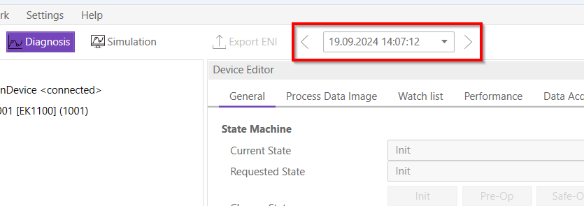
After the snapshot(s) is / are made in diagnosis mode they can be selected in the overview in config mode:
- After the selection switching to diagnosis mode is possible. In the toolbar will be an additional combobox to select the snapshot and switch between them:
8.9.4. Expert
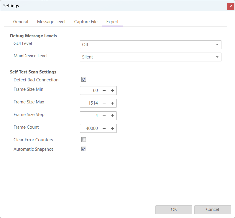
- Debug Message Levels
- GUI Level
Changes the GUI debug message level
- MainDevice Debug Message Level
Changes the MainDevice debug message level
- Self Test Scan Settings
- Detect Bad Connection
(De-)Activates bad connection detection
- Frame Size Min
Changes the min frame size
- Frame Size Max
Changes the max frame size
- Frame Size Step
Changes the frame step size
- Frame Count
Changes the frame count
- Clear Error Counters
Resets the error counters on the MainDevice
- Automatic Snapshots
Enables the creation of a snapshot after running a successful Self Test Scan
8.9.5. Settings File
Inside this file the user can modify all settings, including some that are not present in the settings dialog.
Warning
Only modify this file if you know what you are doing.
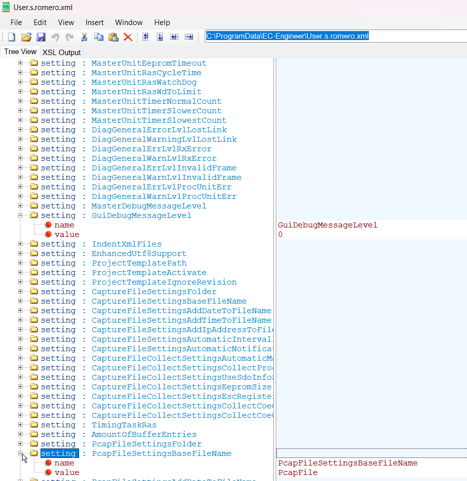
The file can be located either at “C:/ProgramData/EC-Engineer/User.<username>.xml” or insdie the install directory.
8.10. Project Templates
If you have a lot of SubDevices with the same configuration (e.g. PDOs, InitCmds) you can use a project template. In that case new SubDevices will be first copied from this template (if available) and then taken from the ESI cache. This behaviour is also used for the bus scan.
- At the moment there are the following options:
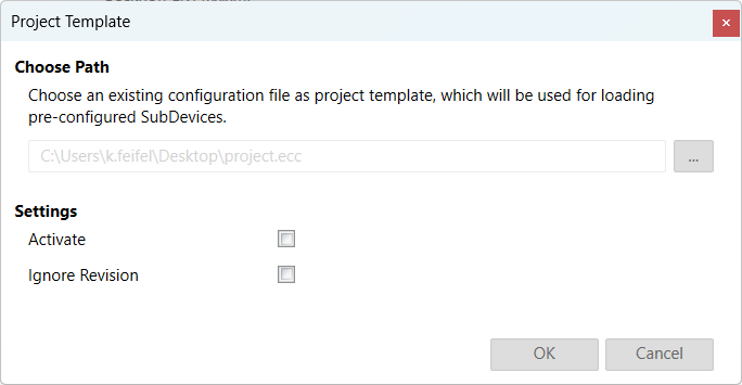
Path: Path to the selected project template
- Settings
- Activate:
True, for activating this project template (necessary if you want to turn it temporary off)
- Ignore Revision:
The revision will be not used as search criteriom
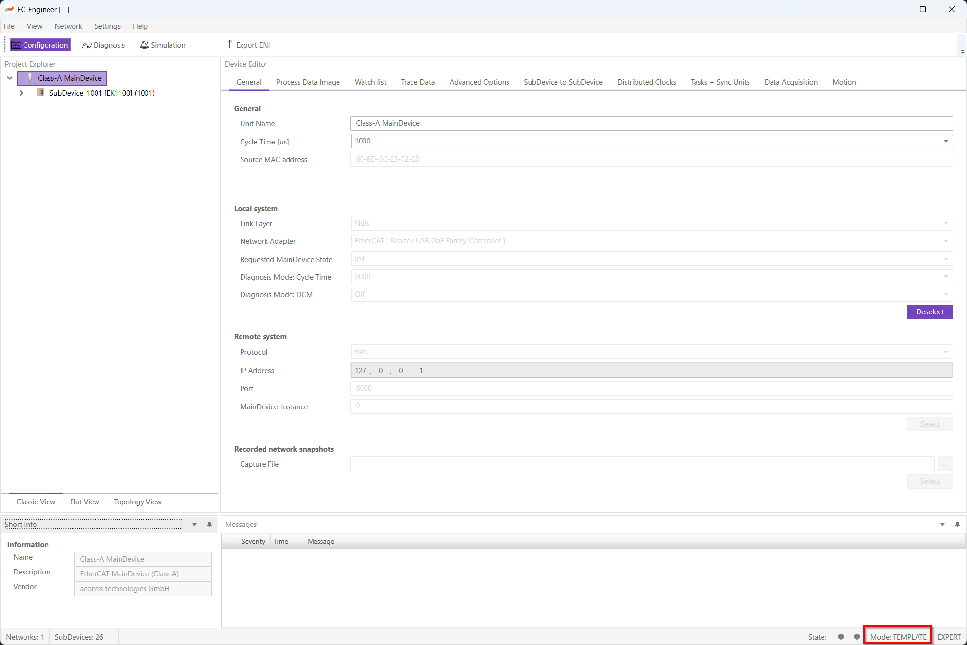
- If the project template mode is active, it will be displayed in the status bar:
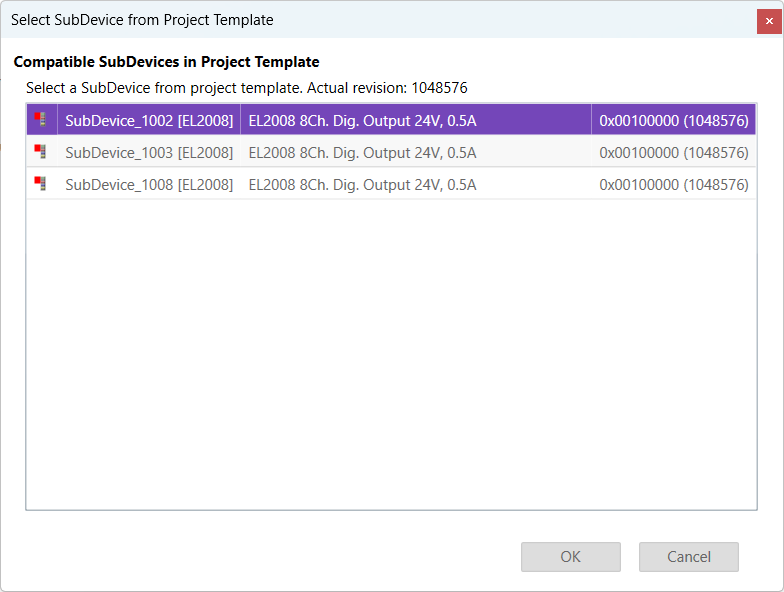
- Normally the first match will be taken from project template. If this is wrong, you can open the context menu and select another one:
8.11. Real-time Support
Normally on Windows you do not have real-time support, but to get DCM in sync you can install the “ECAT driver” in the following modes:
- Network driver
The network driver can be used from the optimized link layers
The real-time support is normally hidden in EC-Engineer. It can be activate by copying the specific link layer libraries into the installation directory of EC-Engineer.
For the local system, EC-Engineer will turn on DCM and use the real-time clock for generating the job task cylces. For more information about how to install the “ECAT driver” please refer the manual of EC-Master Class A DCM on Windows
8.11.1. Optimized Link Layers
- After activating the real-time support the optimized link layer can be selected in the option “Link Layer”:
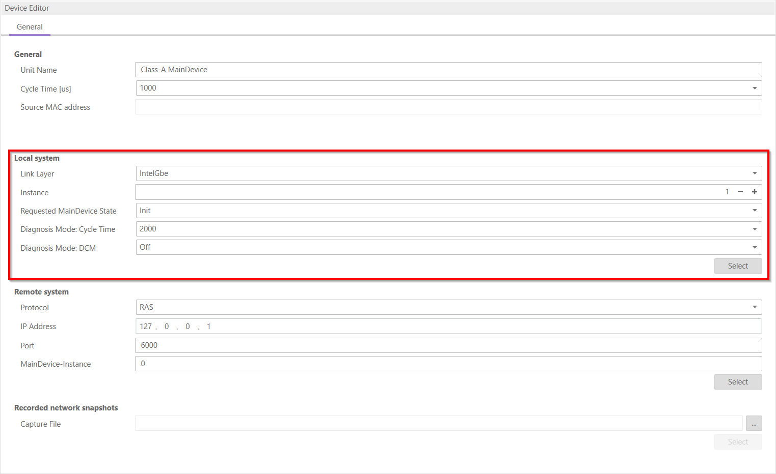
Depending on the link layer type the user can chose the network adapter or the instance.
The following optimized link layers are currenty supported:
emllI8254x.dll (Intel PRO/1000 Network Adapters)
emllI8255x.dll (Intel PRO/100 Network Adapters)
emllIRTL8139.dll (Realtek 8139 Fast Ethernet Adapters)
emllIRTL8169.dll (Realtek Gigabit Ethernet Adapters)
emllICCAT.dll (BECKHOFF CCAT)
For more information about optimized link layers and how to install the ECAT driver please refer the manual of EC-Master Class B EcatDrv for Optimized Link Layers
8.12. Export ENI Variants
- With this function it is possible to export different ENI file variants of an config. Therefore a xml file has to be created. Then it is possible to select this xml file and create more ENI files at once. The xml file should look like this:
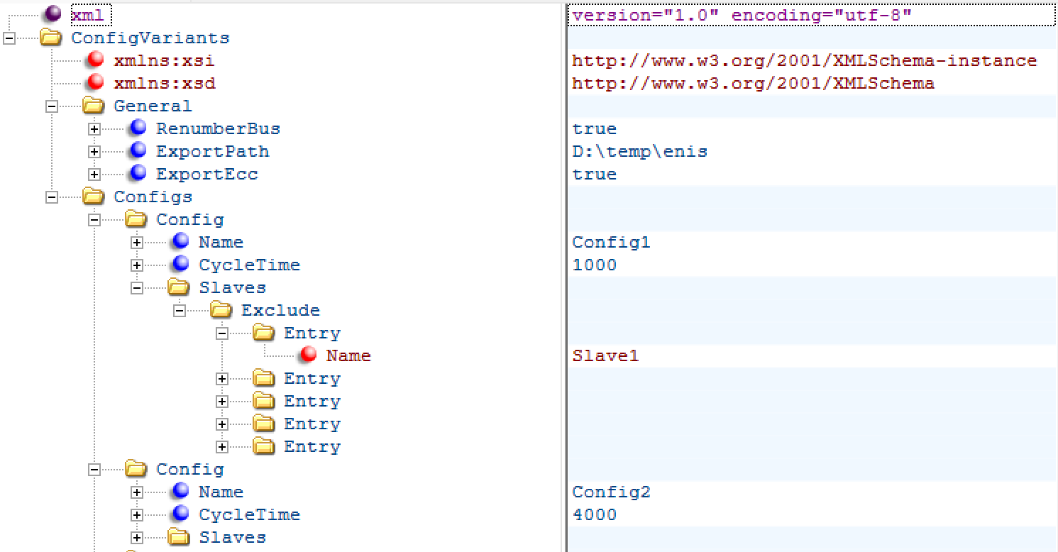
RenumberBus: If this is true, all SubDevices will be enumerated in a row. Otherwise each SubDevice stays with his address.
Export Path: The path were the ENI / ECC files should be saved.
ExportEcc: If true, also the ECC file be exported and not only the ENI.
Each Config needs a name. This name is used for the ENI file and the optional ECC file.
CycleTime (optional): If this is set the cycle time will be changed to this value.
Exclude: To find a SubDevice in the config the name is required. With that it is possible to remove some SubDevices from a big config for example.
Include: To find a SubDevice in the config the name is required. With the include it is possible to easy delete all SubDevices in the config despite except the include ones.
Warning
Please use Exclude OR Include. Both in the same config does not work