5. Configuration Mode
5.1. Overview
The EC-Master needs the EtherCAT-Network-Information (ENI) file to initialize and control the EtherCAT network. In most cases the automatically generated Slave settings can be used to run the EtherCAT network. In this chapter you can read how EC-Engineer helps you to view or adjust those settings.
- At startup of EC-Engineer, the user will see this page:
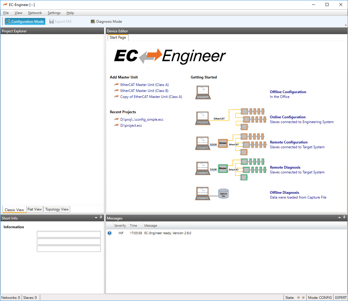
- It consists of three sections:
Add Master Unit: List of available master units
Recent Projects: List of the last five opened projects
Getting Started: List of available run modes
If the user clicks on one of the links, it runs a new master unit, opens an already existing project or switches in the “Getting Started” mode.
5.2. Master Settings
This section includes network related or master related settings. Some of those settings will also affect the “Master” section of the ENI.
5.2.1. Master
- In this tab, the user can configure the name of the master and the cycle time. If he wants to connect to a control system, this can be also configured:
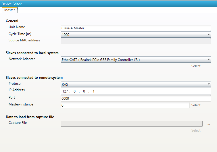
- General
- Unit Name:
Name of the master device
- Cycle Time:
Interval in microseconds in which all EtherCAT commands will be sent from the master. The user can choose between the following values: 125, 250, 500, 1000, 2000 and 4000.
- Source MAC address:
MAC address of the connected system (will be filled during bus scan)
- Slaves connected to local system
- Network Adapter:
Network adapter which is connected to the control system. In newer versions it is also a possibility to select the Link-Layer.
- Slaves connected to remote system
- Protocol:
- Protocol of the remote system
RAS (Default port is 6000)
- Mailbox Gateway (Default port is 34980)
EC-Master V3.0.1.22 and above
TwinCAT 3.1.4024 or TwinCAT 3.1.4022.30 and above
- IP Address:
IP address of the remote system, which is connected to the control system
- Port:
Port of the remote system, which is connected to the control system
- Master-Instance:
Used to determine which master instance should be used in the remote system (Master supports up to 10 instances).
- Data to load from capture file
- Capture File:
Path to the capture file, which contains one ore more snapshots
5.2.2. Process Data Image
- In this tab, the user can see all variables of the process data image. If he wants, he can also export the list:
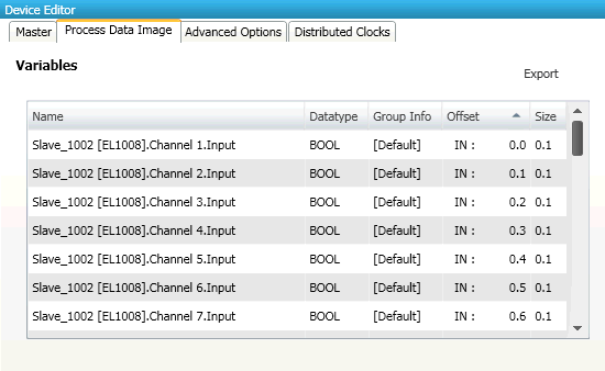
- If user wants to export the variables, he will see the following dialog:
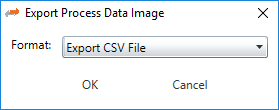
- Export Formats:
CSVFile (Semicolon separated text file)CSV PLCFile (Semicolon separated text file, where offsets are in PLC format)PD LayoutFile (C-Header file which can be used from EC-Master-Demo application)XMLFile (Like ProcessImage inENI)
5.2.3. EtherCAT P Overview
- In this tab, the user can check the EtherCAT P system, if there are EtherCAT P slaves in the configuration. For those EtherCAT P slaves, he can calculate and check the power consumptions in the EtherCAT P segments based on cables and loads:
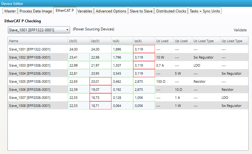
In the ComboBox the user can switch between all Power Sourcing Devices (PSD) in the configuration. In the grid are shown all the supplied slaves from the selected PSD, with the calculated voltages and currents and the selected loads. The values which are to high or to low are marked red.
Hint
These values are not relevant for the ENI-File. They are just a help for the user what might not work. The ENI File can be exported anyway.
On the Validate Button, the user can check the whole configuration. If there is an error somewhere, the correspondending PSD is selecte. If there are no errors the user will get a message box.
5.2.4. Variables (Expert)
- In this tab, the user can add trace variables:
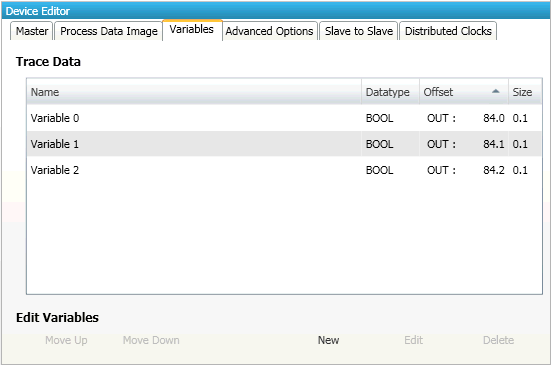
- Trace Data
Trace variables which can be added from the user.
- Buttons
- New/ Edit/Delete:
Used for changing the list.
- Up/Down:
Moving the selected variable up or down
5.2.5. Advanced Options (Expert)
- In this tab, the user can change master specific settings or he can change slave specific settings which will be applied to all slaves:
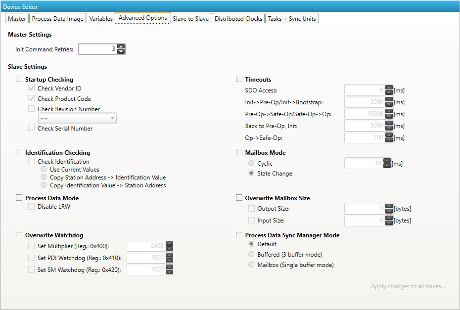
- Master Settings
Init Command Retries: Number of retries, to handle transmission errors.
- Slave Settings
Slave settings can be applied to all slaves with one click on the button Apply changes to all slaves. For a detailed description of the Advanced Slave Options, see Advanced Slave Options (Expert).
- Identification Checking
Use Current Values Identification Checking will be activated for all slaves with the current values
Important
If current is 0, the Identification is not activated!
Copy Station Address –> Identification Checking will be activated for all slaves with the station address as identification value
Copy Identification Value –> Identification Checking will be activated for all slaves and the identification value is also used as station address
5.2.6. Slave to Slave (Expert)
In this tab, the user can configure the slave to slave communication by connecting 2 variables or PDOs.
This tab consists of 2 views:
- Default view
In this view, the user can configure the slave to slave communication by using copy infos in
ENIfile. This is the default way.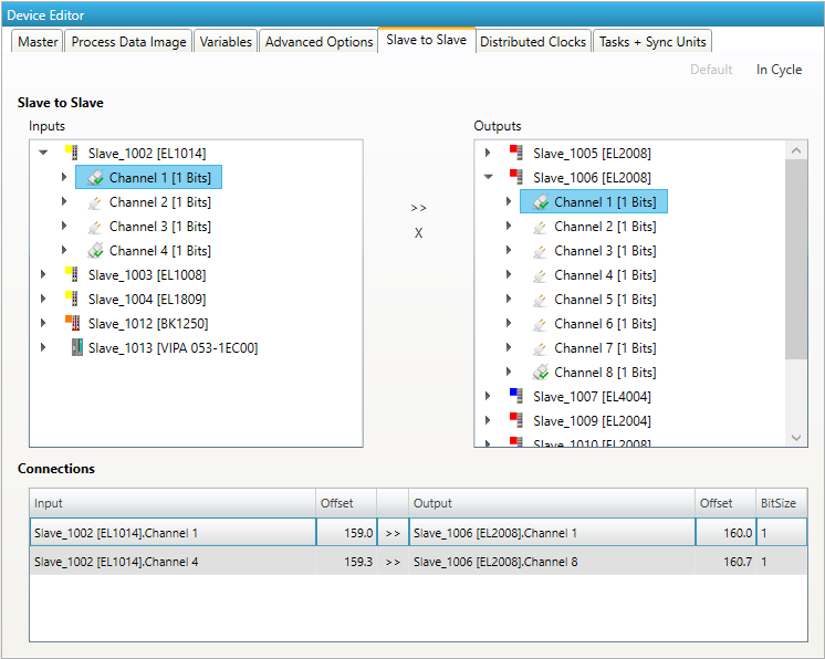
- In cycle view
In this view, the user can configure the on cycle slave to slave communication by setup the process image and the FMMU in a way that inputs of the source slave will be directly written into the outputs of the destination slave during one cycle.
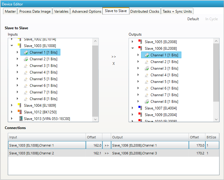
- Limitations of one cycle slave to slave communication:
Input slave must be located before output slave
Complete sync unit of the slave must be connected (this means all PDOs of a sync unit must be connected and not only one variable)
5.2.7. Distributed Clocks (Expert)
- In this tab, the user can change distributed clock related settings:
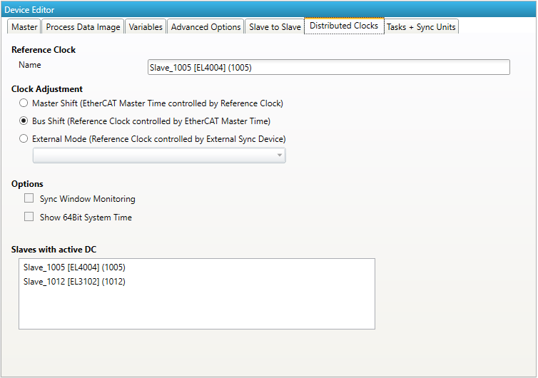
- Reference Clock
- Name:
Name of the reference clock. By default, this is the first slave with DC support.
- Clock Adjustment
- Master Shift:
The reference clock controls the Master time
- Bus Shift:
The Master time controls the reference clock
- External Mode:
The reference clock is controlled by an external sync device
- Options
- Sync Window Monitoring:
A command (datagram) will be inserted in the cyclic frame to read the ESC registers 0x092C. If this is selected the master will throw a notification.
- Show 64Bit System Time:
Master supports slaves with 32bit and 64bit system time register (0x0910). If this is selected he will interpret it as 64bit system time.
- Slaves with active DC
Shows a list of all slaves with active DC.
5.2.8. Tasks + Sync Units (Expert)
- In this tab, the user can define additional cyclic tasks and master sync units. After adding a new master sync unit, the user can assign one or more slave sync units on tab to this master sync unit:
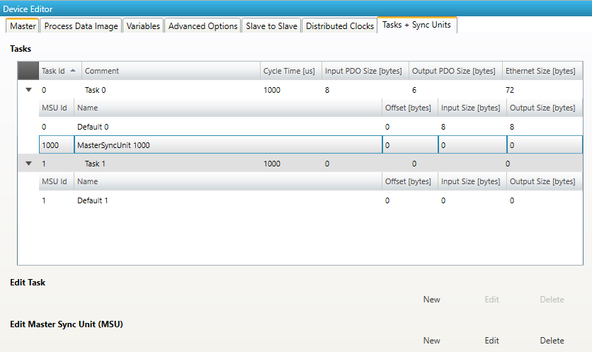
- Tasks:
List of cyclic tasks and master sync units.
- Buttons:
New/Edit/Delete: Used for changing the list.
- If user wants to edit a task, he will see the following dialog:
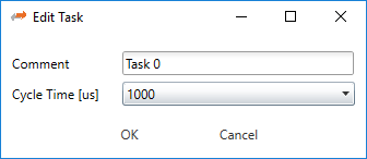
- Comment:
Comment of this task (will be written to
ENIfile)- Cycle Time:
Cycle time of this task
- If user wants to edit a master sync unit, he will see the following dialog:
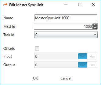
- Name:
Name of this master sync unit (will be written to
ENIfile)- Sync Unit Id:
- Id of this master sync unit (will be written to
ENIfile). ID 0 .. 9: Generated / internal master sync unit
ID 10 .. 999: Generated / internal master sync unit for groups
ID 1000 .. 2000: User defined master sync unit
- Id of this master sync unit (will be written to
- Task Id:
Task Id to which is this master sync unit assigned
- Offsets:
Activate to pin this master sync unit to a specific offset
- Input:
Input offset of pinned master sync unit
- Output:
Output offset of pinned master sync unit
5.2.9. Data Acquisition (Expert)
In this tab, the user can configure our Data Acuisition (DAQ) library. This library can used from EC-Master to record process data in realtime.
- After adding a new recorder, the user can select the variables which should be recorded and specify some triggers:
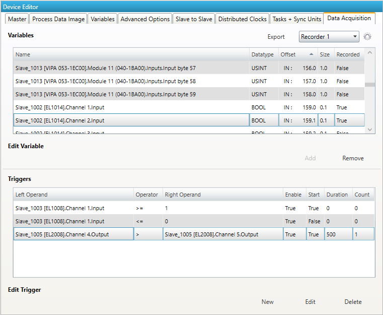
- Variables:
- Add/Remove:
Used for adding or removing the selected variable to the recording.
- Triggers:
- New/Edit/Delete:
Used for changing the trigger list.
- If user wants to edit a recorder, he will see the following dialog:
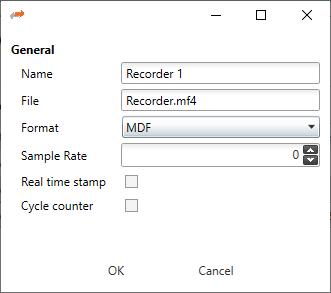
- Name:
Name of the recorder
- File:
Absolute path of the recorder file on the master system
- Format:
- Format of the recorder file, e.g.
MDF(Measurement Data Format)CSV(Comma Separated Values)
- Sample Rate:
Sample rate of the recorded data e.g. every cycle or every second cycle, …
- Real time stamp:
Adds a real time stamp to the recorded data
- Cycle counter:
Adds a cycle counter to the recorded data
- If user wants to edit a trigger, he will see the following dialog:
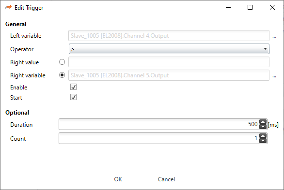
- General
- Left variable:
Name of the left variable
- Operator:
Operator of the trigger (e.g. =, >, >=, <, <=, !=)
- Right value:
Value of the right operand to compare the left variable against a static value e.g. trigger, if variable is greater than 5
- Right variable:
Name of the right variable to compare the left variable against the value of another variable e.g. trigger, if variable 1 is smaller than variable 2
- Enable:
Enabled or disabled trigger (can be enabled from application later)
- Start:
Start or stop trigger
- Optional
- Duration:
Duration in ms (0 = infinite) e.g. trigger should start recording for 500 ms
- Count:
Trigger count (0 = infinite) e.g. trigger should hit only for 5 times
For more information please refer the manual of the EC-Master-Data-Acquisition-Library.
5.2.10. Motion Settings (Motion Mode only)
- In this tab, the user change settings for the Motion Demo Configuration. It is also possible to export the
DemoMotionConfig.xmlfile: 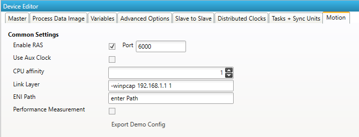
5.2.11. Scripts
- In this tab, the user can select scripts that are executed in the different modes. The tab is only visible when the script mode is activated in the
EMIfile: 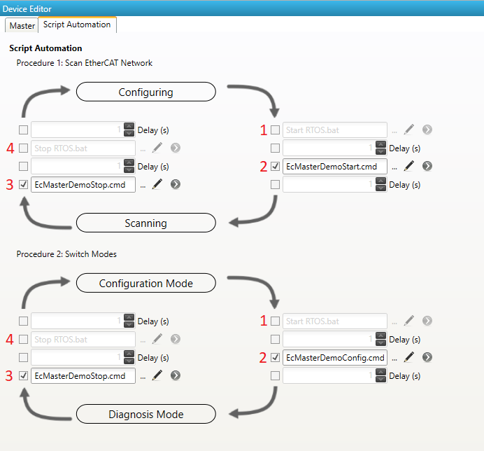
The first procedure is for scanning the network. There is the possibility of starting two scripts before the scan, and two scripts after the scan. It is also possible to set a delay between them. A usecase for this could be to start e.g. LxWin –> then start the master on the real-time system –> scan the network –> stop the master –> stop LxWin.
The second procedure is for switching the modes (configuration and diagnosis). The user can e.g. start LxWin –> start the master –> switch to diagonis. On switching back the user can stop the master and stop LxWin. Or it is also possible not to stop the LxWin for example.
The and circles are the starting points. Then the scripts are called clockwise following the arrows and the red numbers.
5.2.12. Simulator Settings
- In this tab, the user can change the settings for the simulator. The tab is only visible when the user uses EC-Simulator
EMIor when the Master Unit has an linked simulator unit. The linked simulator unit can be created through the context menu of the master unit, or when the simulator link layer is selected: 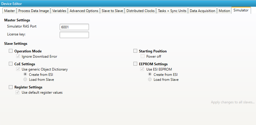
- Simulator RAS Port:
The port which is opend through the simulator link layer
- License key:
The license key for the simulator
- Slave Settings:
- Operation Mode:
Ignore Download Error
- CoE Settings:
Select which CoE should be used in
EXI- Register Settings:
Select if register should be in
EXI- Starting Position:
Select if slave shall be powered on or off on start
- EEPROM Settings:
Select which EEPROM values should be used
The EXI file can be exported through the Export EXI button right from the Export ENI Button or through the context menu.
5.3. Slave Settings
This section includes slave related settings. The most of all settings will affect the “Slave” section of the ENI.
5.3.1. General
- In this tab, the user can change general slave settings like station address or the name of the slave. He has also the possibility to change his predecessor device:
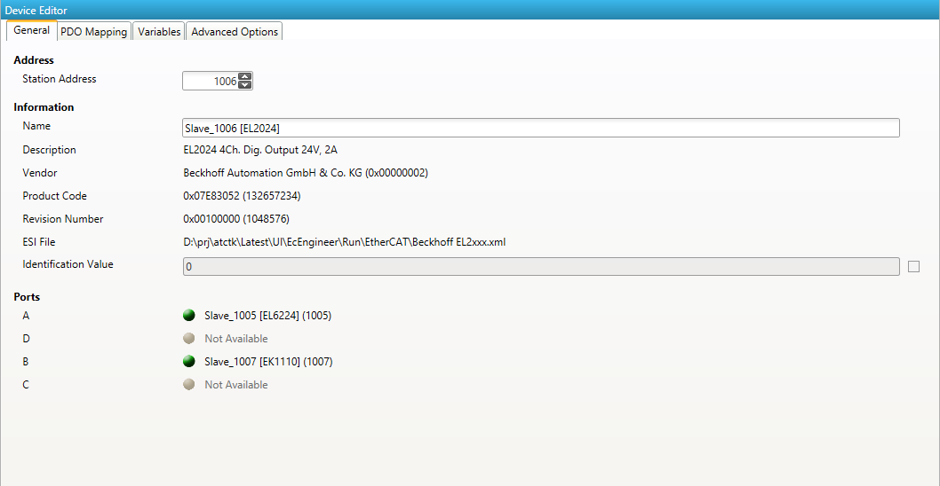
- Address
- Station Address:
Station address of the slave. By default, the first station address is 1001.
- Information
- Name:
Name of the slave. By default the following format is used “Slave_N [TYPE]”
- Description:
Description of the slave (Read from
ESIfile)- Vendor:
Name of the vendor the slave
- Product Code:
Product Code of the slave
- Revision Number:
Revision Number of the slave
- ESI File:
Name of the
ESI `file where the description of the slave is stored. :file:`ESIfiles can be managed by using the ESI-Manager- Identification Value:
Identification Value of the slave
- Ports
- Connected Devices:
List of connected devices
- Predecessor Device:
Name of the predecessor device. If topology should be changed, please use the Edit Topology dialog
5.3.2. Modules
- In this tab, the user has can assign modules into the specific slots. He can also change the setting for downloading the slot configuration to the slave:
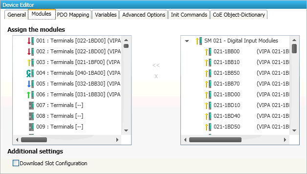
- Connect module to slot (“<<”)
Used for connecting the selected module (from the right list) to the selected slot (from the left list). If the slot is already connected, the module will be inserted and the subsequent modules will be moved (if this is supported from the slave)
- Disconnect module from slot (“X”)
Used for disconnecting the selected slot (left list)
Note
The modules can be also connected and disconnected by using the context menu in the project explorer.
5.3.3. PDO Mapping
This tab consists of 2 views:
5.3.3.1. PDO
- In this tab, the user can see the current PDO mappings. For some Slave types the user can activate or deactivate some PDO configurations:
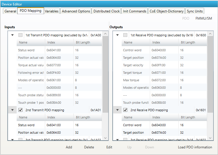
- Lists of inputs or outputs
- Checkbox:
Signals if PDO will be used for the current configuration or not.
- Buttons (Expert mode only!)
- Add/Delete/Edit:
Used for changing the lists, if it is allowed by the
ESI. First the list which should be changed must be selected.- Up/Down:
Moving the selected PDO in the selected list up or down
- Load PDO information:
If EC-Engineer is connected to the control system, the user can load the PDO information directly from the slave
- Context Menu
- Both lists provide a context menu:
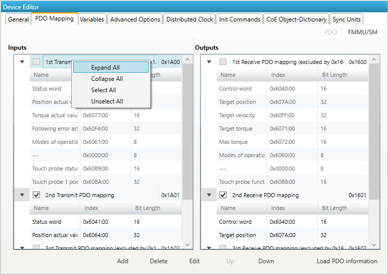
- If user wants to add or edit a PDO, he will see the following dialog:
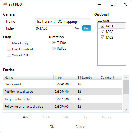
- General:
- Name:
Name of the PDO
- Index:
Index of the PDO (can be entered in hexadecimal or decimal)
- Flags:
- Mandatory:
PDO cannot be deleted
- Fixed Content:
Content of PDO cannot be changed
- Virtual PDO:
PDO has no entries
- Direction:
- TxPdo:
Input PDO
- RxPdo:
Output PDO
- Sync Manager:
Selected the Sync Manager, which should be used (only visible if more than one can be used)
- Exclude:
Select the PDOs which cannot be activated if this PDO is activated
- Entries:
List of configured PDO entries
- If user wants to add a PDO entry, he will see the following dialog:
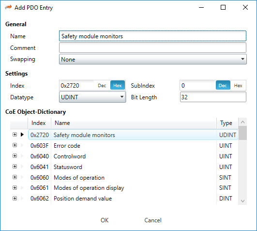
- General
- Name:
Name of the PDO entry
- Comment:
Commet of the PDO entry
- Swapping:
Swapping mode of the PDO entry
- Settings
- Index:
Index of the PDO entry (can be entered in hexadecimal or decimal)
- Subindex:
Subindex of the PDO entry (hexadecimal)
- Datatype:
List of available datatypes
- Bit Length:
Length of the PDO entry in bits
CoE Object-Dictionary (loaded only if Object-Dictionary is supported by slave)
- If user wants to edit a PDO entry, he will see the following dialog:
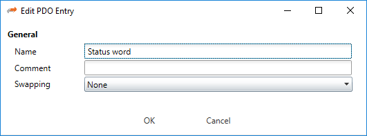
- General
- Name:
Name of the PDO entry
- Comment:
Commet of the PDO entry
- Swapping:
Swapping mode of the PDO entry
5.3.3.2. FMMU/SM
- In this tab, the user can see some information about FMMU and SyncManager:
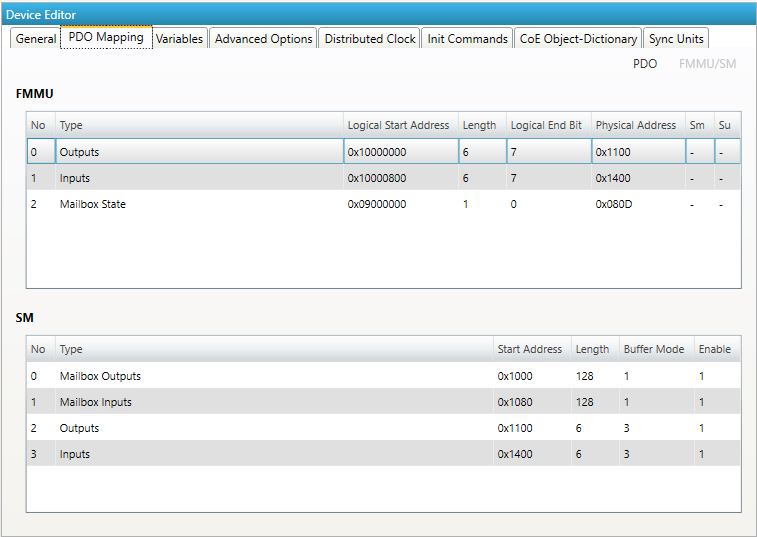
- Lists of FMMUs
Available FMMUs comes from the
ESIfile.- Lists of SyncManagers
Available SyncManagers comes from the
ESIfile.
5.3.4. Variables
- In this tab, the user can see the variables of the slave and if it is allowed he can also add/edit/delete/move variables:
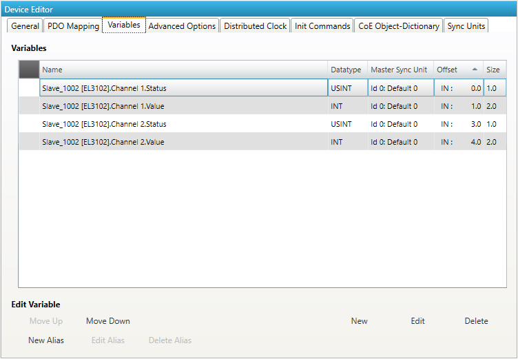
- Lists of Variables
Variables comes from the
ESIfile or will be generated from the configurator.- Buttons
- New/Edit/Delete:
Used for changing the list.
- Up/Down:
Moving the selected variable up or down
- New/Edit/Delete Alias:
Used for changing alias variables
- If user wants to add a variable, he will see the following dialog:
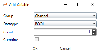
- Options
- Group:
List of possible groups, where the new variable should be added
- Datatype:
List of possible datatypes of the new variable
- Count:
Number of variables, which should be added
- Combie:
Combines all variables to an array
- If user wants to edit a variable, he will see the following dialog:
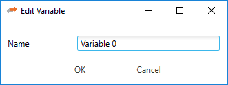
- Options
- Name:
Name of the variable, which can be changed from the user
- If user wants split a variable into multiple parts to build e.g. a structure, he can add an alias to a vailable. In that case he will see the following dialog:
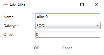
- Options
- Name:
Name of the alias
- Datatype:
List of possible datatypes of the new alias
- Offset:
Bit offset of the alias
- If user wants to edit a alias, he will see the following dialog:
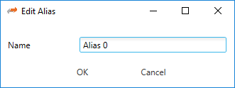
- Options
- Name:
Name of the alias, which can be changed from the user
5.3.5. EtherCAT P
- In this tab, the user can configure the selected EtherCAT P slave. The Tab is only visible when the selected slave is an EtherCAT P slave:
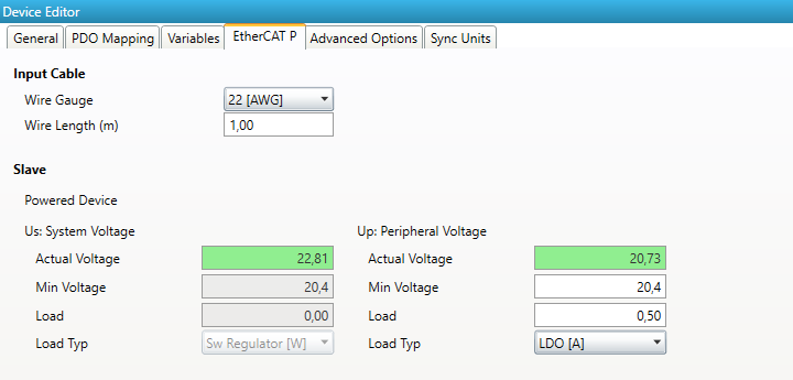
- Wire Gauge:
The wire type of the input cable
- Wire Length:
The wire length of the input cable
- Us:
- System Voltage
- The system voltage shall supply all internal and externally connected types of sensors and inputs. All bus system relevant parts of the device shall completely be powered by the Us.
- Actual Voltage:
The actual voltage at the slave
- Min Voltage:
The min Voltage the slave needs. Value is from
ESIbut also editable.- Load:
The Load which is externally needed.
- Load Type:
The Load Type of the externally needed load
- Up:
- Peripheral Voltage:
- Up is used to supply internal and externally connected actuators and outputs.
- Actual Voltage:
The actual voltage for the outputs
- Min Voltage:
The min Voltage the slave needs. Value is from
ESIbut also editable.- Load:
The Load which is externally needed.
- Load Type:
The Load Type of the externally needed load
- Load Types:
Sw Regulator in Watt LDO in Ampere Resistor in Ohm
5.3.6. Advanced Slave Options (Expert)
- In this tab, the user can change advanced options of the slave:
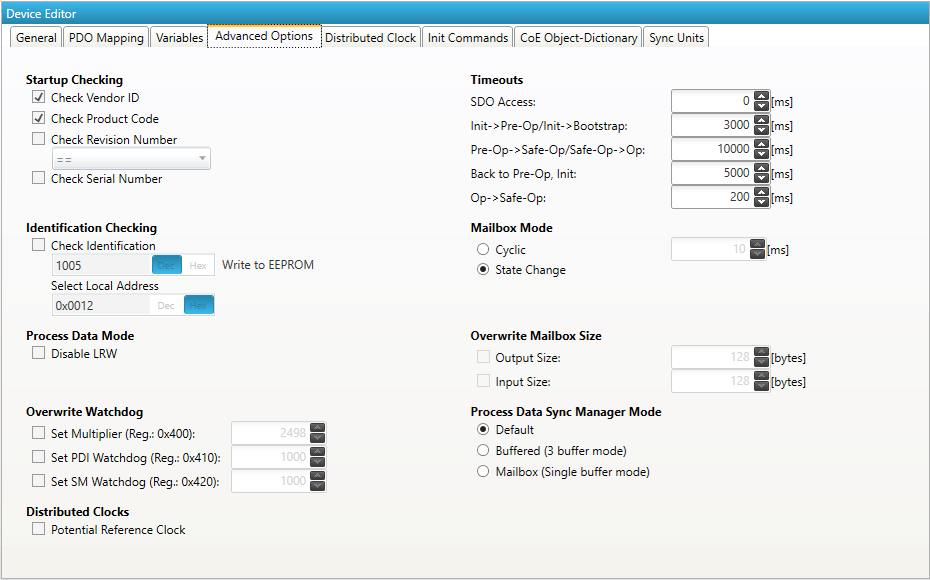
- Startup Checking
- Master will check the Vendor ID, Product code, Revision number if the state machine changes from INIT to PREOP of the slave. Revision number can be verified by six ways:
“==” –> HI word is equal, LO word is equal
“>=” –> HI word is equal or greater, LO word is equal or greater
“LW ==” –> HI word is equal
“LW ==, HW >=” –> LO word is equal, HI word is equal or greater
“HW ==” –> LO word is equal
“HW ==, LW >=” –> HI word is equal, LO word is equal or greater
- Identification Checking
If ‘Check Identification is selected, the Identification Value of the slave is checked. In the ‘Select Local Address’ Box is the register of the Identification Value.
- Process Data Mode
Disable LRW: Determines whether LRD/LWR command or the LRW command is used for accessing process data. Cable redundancy needs LRD/LWR, Slave-to-slave-copy needs LRW.
- Watchdog
- Set Multiplier:
Writes the configured value to the corresponding slave register: 0x0400
- Set PDI Watchdog:
Writes the configured value to the corresponding slave register: 0x0410 (0 = Watchdog is disabled)
- Set SM Watchdog:
Writes the configured value to the corresponding slave register: 0x0420 (0 = Watchdog is disabled)
- Distributed Clocks
- Potential Reference Clock: Set to use slave as a potential reference clock
This might be useful, if e.g. a hot connect slave, which is used as reference clock, was disconnected from the network
In that case the EC-Master searches for the first potential reference clock
If no potential reference clock slave was found, the first DC slave will be used
- Timeouts
- SDO Access:
Internal master timeout which is used for accessing the SDO (0 = Use internal default value of the master)
- Init –> PreOp:
Internal master timeout with is used for changing slave state
- Pre-Op –> Save-Op or Safe-Op –>Op:
Internal master timeout with is used for changing slave state
- Back to Pre-Op, Init:
Internal master timeout with is used for changing slave state
- Op –> Safe-Op:
Internal master timeout with is used for changing slave state
- Mailbox Mode
- Cyclic:
Interval in milliseconds within the input mailbox will be read (polling mode)
- State Change:
The input mailbox will be read only if the status bit is set
- Overwrite Mailbox Size
- Output Size:
Overwrites mailbox output size
- Input Size:
Overwrites mailbox input size
- Process Data Sync Manager Mode
- Default:
Uses sync manager mode from
ESIfile- Buffered (3 buffer mode):
Enables 3 buffer mode
- Mailbox (Single buffer mode):
Enables single buffer mode
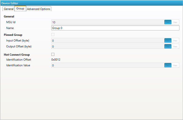
5.3.7. (Hot Connect) Groups
- In this tab, the user can choose if this group has a fixed offset in the process data image or if this group is a hot connect group:
Note
Tab is only visible if slave is the first member of a group.
- General
- MSU Id:
Generated Master Sync Unit Id
- Name:
Name of the group
- Pinned Group
- Input Offset:
Fixed input offset of the group in the process data image in bytes
- Output Offset:
Fixed output offset of the group in the process data image in bytes
- Hot Connect Group
- Identification Offset:
Register offset where the identification can be read from the slave
- Identification Value:
Hardware identification value or configured station alias address can be used. For more information about the configured station alias address, see EEPROM (Expert)
- A new group can be created by selecting all slaves (by using the SHIFT key or the CTRL key), open the context menu and select Create Group in the project explorer:
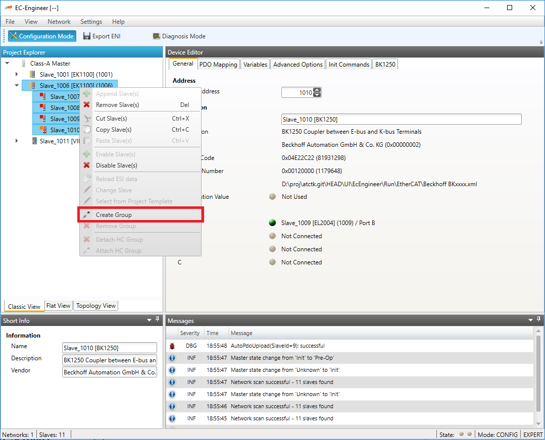
- The new group can be modified by selecting the head slave of this group and open tag :
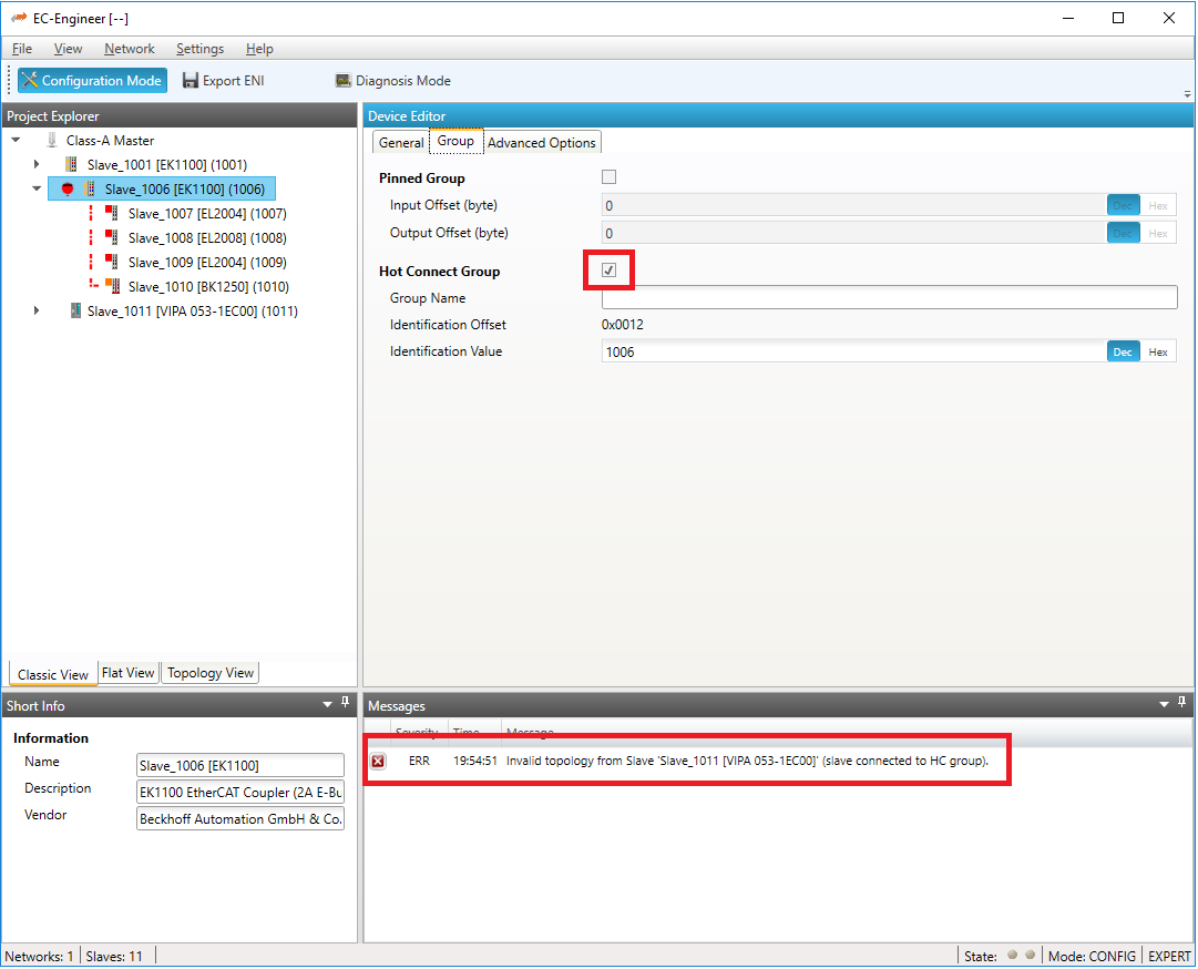
On this tab, the user can pin this group of slaves to a specific offset in the process image and / or build a hot connect group. If we do this, in that case this will generate an invalid topology error, because a normal slave is still connected to this hot connected, which is not allowed.
- In that case we can use “cut & paste” to solve this issue by connecting this hot connect group to the end of the slaves:
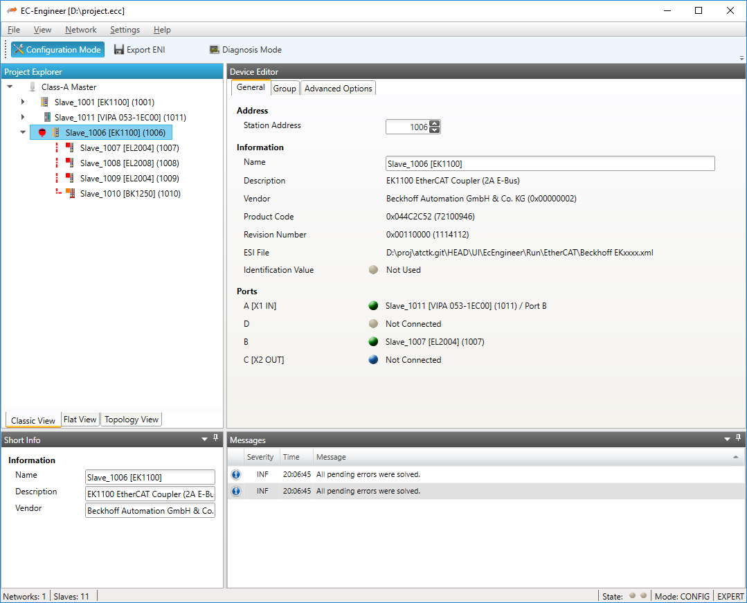
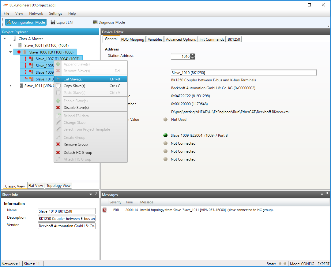
- Now, we have a hot connect group which is connectable only to slave 1011. If we want to connect this group to any slave on the network, we have to detach the group:
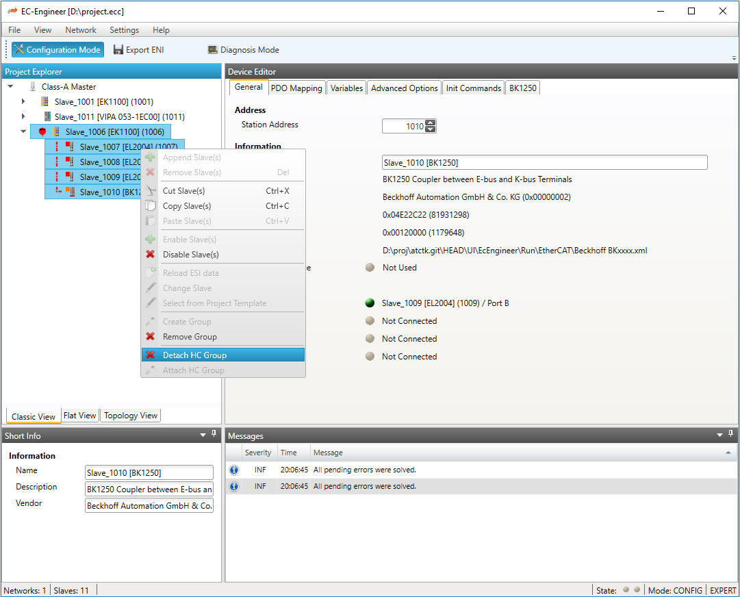
A group can be deleted by selecting the head slave of this group, open the context menu and select “Remove Group” in the project explorer (only attached HC groups can be deleted).
- Possible group related error messages:
Detached group can not be attached to the old position in the tree (e.g. previous slaves was deleted or disabled) the head slave of the group will be reported as “not connected”. In that case the user can connect the head slave by using “cut” and “paste”.
Invalid topology from slave (fixed HC group on master) was displayed: this means that the first HC group which is connected to the master should be detached, because this is not valid in the
ENIfileInvalid topology from slave (slave connected to HC group) was displayed: this means that a normal slave is connected to a hot connect group and should be also moved also into a hot connect group or moved to another position in the tree
5.3.8. Ethernet (EoE)
- In this tab, the user can activate EoE support and change the settings:
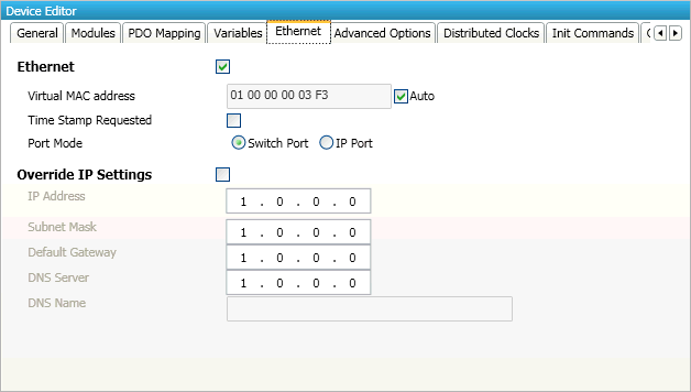
- Ethernet (activates EoE support):
- Virtual MAC address:
Virtual MAC address. If “Auto” is checked, the Virtual MAC address will be generated from the Station Address, e.g. Station Address is “1010” (= 0x03F2), will generate the Virtual MAC address: “01 00 00 00 03 F2”
- Time Stamp Requested:
Slave will response with the exact send time and the same Frame Number and he should response as soon as possible
- Port Mode:
Slave can run in “Switch Port” or in “IP Port” mode
- Override IP Settings:
All IP settings will be overwritten from master like IP Address, Subnet Mask, Default Gateway, DNS Server and DNS Name.
5.3.9. Distributed Clock (Expert)
- In this tab, the user can change distributed clock related settings:
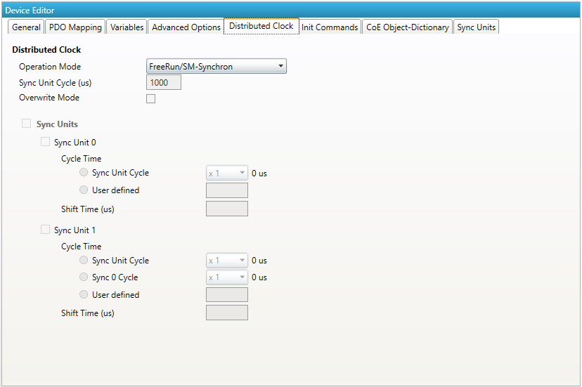
- Reference Clock
- Operation Mode:
Selectable DC operation modes. The modes cannot be edited.
- Sync Unit Cycle:
Base interval in microseconds which will be used from master (see Master)
- Overwite Mode:
Overwrites the settings of the selected operation mode (might be necessary, if the slave doesn’t offer the right operation mode)
- Sync Units
- Sync Unit 0
- Cycle Time
- Sync Unit Cycle:
Unit is synchronized relative to the Unit Cycle
- User defined:
Unit has its own interval
- Shift Time
Unit is adjusted by the shift time
- Sync Unit 1
- Cycle Time
- Sync Unit Cycle:
Unit is synchronized relative to the Unit Cycle
- Sync 0 Cycle:
Unit is synchronized relative to the first Sync Unit
- User defined:
Unit has its own interval
- Shift Time
Unit is adjusted by the shift time
5.3.10. Init Commands (Expert)
- In this tab, the user can view the current configured init commands and if it is allowed he can also add/edit/delete init commands:
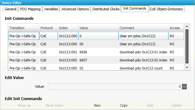
- Lists of Init Commands
Init Commands comes from the
ESIfile or will be generated from the configurator. The “Access” column tells the user if this Init Command can be edited (RW = Read/Write) or not (RO = Read-Only).- Buttons
- New/Copy/Edit/Delete:
Used for changing the list
- Up/Down:
Moving the selected Init Command up or down
- At the moment only Init Commands of the CoE- and SoE- Protocol can be added or changed. If the user wants to do this he will see the following dialog (CoE):
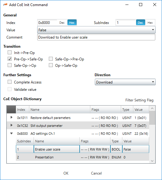
- General
- Index:
CoE-Index of the Init Command
- SubIndex:
CoE-SubIndex of the Init Command
- Value:
Value of the Init Command, which should be written in the chose transition (only available if direction is set to “Download”). If type of value is unknown, the hex format must be used like “00 11 22 33 …”.
- Comment:
Comment of the Init Command
- Transition
Determines in which transition the Init Command will be executed
- Further Settings
Determines if the complete SDO object should be written/read
- Direction
- Determines the direction of the Init Command
- Download:
Writes value to slave
- Upload:
Reads value from slave (e.g. necessary if value must be confirmed)
- For SoE the user will see the following dialog:
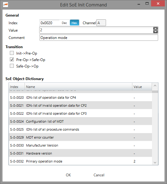
- General
- Index:
SoE Idn of the Init Command
- Channel:
The channel of the Init Command
- Value:
Value of the Init Command
- Comment:
Comment of the Init Command
- Transition
Determines in which transition the Init Command will be executed
5.3.11. CoE Object-Dictionary (Expert)
- In this tab, the user can see and edit the offline CoE object dictionary.
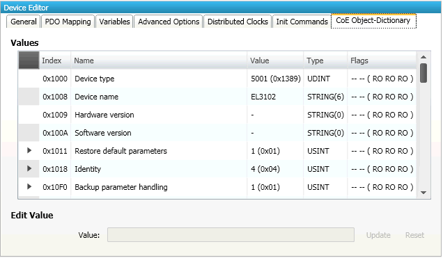
- Lists of CoE Object-Dictionary entries
Entries comes from the
ESIfile or will be generated from the configurator.- The “Flags” column tells the user if this entry is an PDO entry and if it can be edited
“AA BB (CC DD EE)”
AA = Mapping as RX PDO or not
BB = Mapping as TX PDO or not
CC = Access rights for PreOp (RO, WO, RW)
DD = Access rights for SafeOp (RO, WO, RW)
EE = Access rights for Op (RO, WO, RW)
- Buttons
- Update:
Changes the selected entry
- Reset:
Resets the selected entry to
ESIdefault
5.3.12. SoE Object-Dictionary (Expert)
- In this tab, the user can see and edit the offline SoE object dictionary.
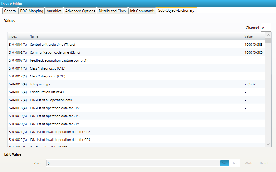
- Lists of SoE Object-Dictionary entries
Entries comes from the
ESIfile- Buttons
- Update:
Changes the selected entry
- Reset:
Resets the selected entry to
ESIdefault
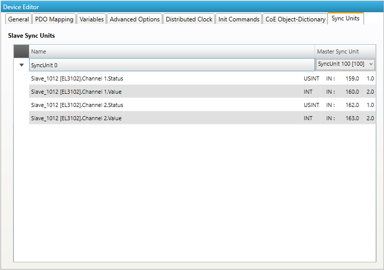
5.3.13. Sync Units (Expert)
- In this tab, the user can assign a slave sync unit to a specific master sync unit by using the combobox column “Master Sync Unit” (only visible if user has defined additional master sync units).
5.3.14. Slave Specific Tabs (Expert)
Some slaves needs special configuration options. If this is necessary we display a slave specific tab.
Important
At first “Activate” have to be set, to activate the automatism for generating PDOs and Init Commands.
This tab will be displayed for the following slaves:
- EL6731-0010 PROFIBUS DP Slave
- General:
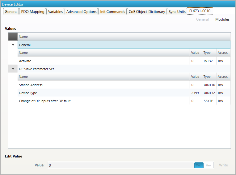
Activate: Activates the automatism for generating PDOs and Init Commands
- DP Slave Parameter Set
- Station Address:
DP station address of the DP slave (permitted values: 0-125)
- Device Type:
DP Ident Number of the DP slave
- Modules:
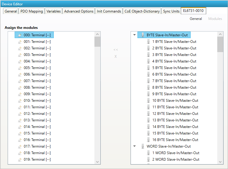
- Connect modules to slot (“<<”)
Used for connecting the selected modules (from the right list) to the selected slot (from the left list).
- Disconnect module from slot (“X”)
Used for disconnecting the selected slot (left list)
- EL6631-0010 PROFINET IO Device
- General:
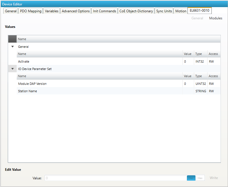
Activate: Activates the automatism for generating PDOs and Init Commands
- IO Device Parameter Set
- Module DAP Version:
Module DAP version of the DP slave (0 = Auto, 1 = V2.0, 2 = V2.25, 3 = V2.3, at least FW 02, 4 = V2.31, at least FW 03, 5 = V2.32, at least FW 08, 6 = V2.33, at least FW 10, 7 = V2.33, at least FW 14)
- Station Name:
Station name of the DP slave (max: 240 chars)
- Modules:
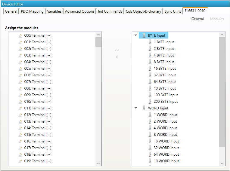
- Connect module to slot (“<<”)
Used for connecting the selected module (from the right list) to the selected slot (from the left list).
- Disconnect module from slot (“X”)
Used for disconnecting the selected slot (left list)
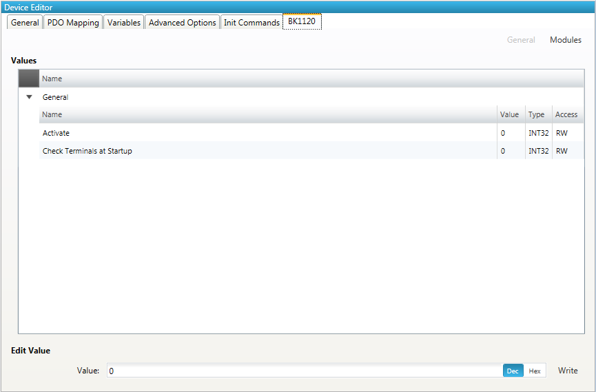
- K-bus Coupler / IP Link Coupler
- Supported devices:
- K-bus Coupler
BK1120
BK1150
BK1250
- IP Link Coupler
IL2300-B110
IL2301-B110
IL2302-B110
- General:
- Activate:
Activates the automatism for generating PDOs and Init Commands
- Check Terminals at Startup:
Activates the automatism for checking terminals at startup
- Terminals:
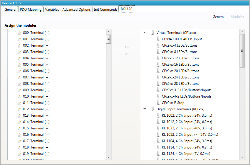
- Connect terminials to slot (“<<”)
Used for connecting the selected terminal (from the right list) to the selected slot (from the left list).
- Disconnect terminals from slot (“X”)
Used for disconnecting the selected slot (left list)
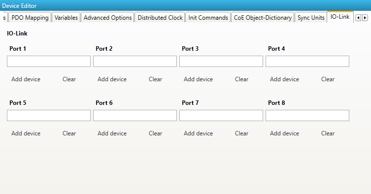
5.3.15. IO–Link
In this tab, the user can configure the IO-Link terminal EL6224, EP6224 and EP(P)6228. He can add different devices to the ports (IODD). The user can see 4 or 8 ports. Depends on the configured slave.
- Please be careful when using the EP(P)6228 that there are no double assignments through the Modules-Tab:
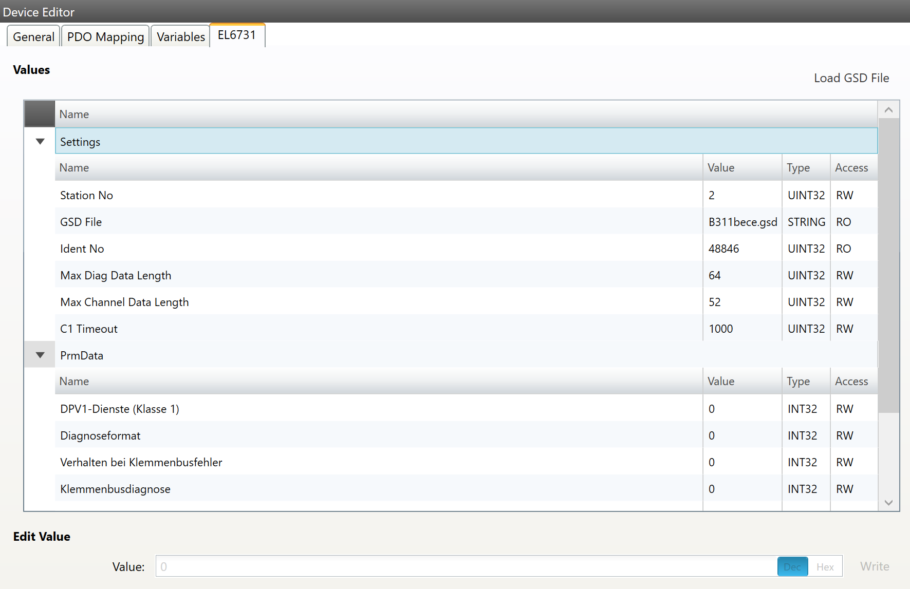
5.3.16. Profibus Master (EL6731)
- In this tab, the user can configure the Profibus Master EL6731. New Profibus modules can be added in the tree. Right click an then ‘Append module’.
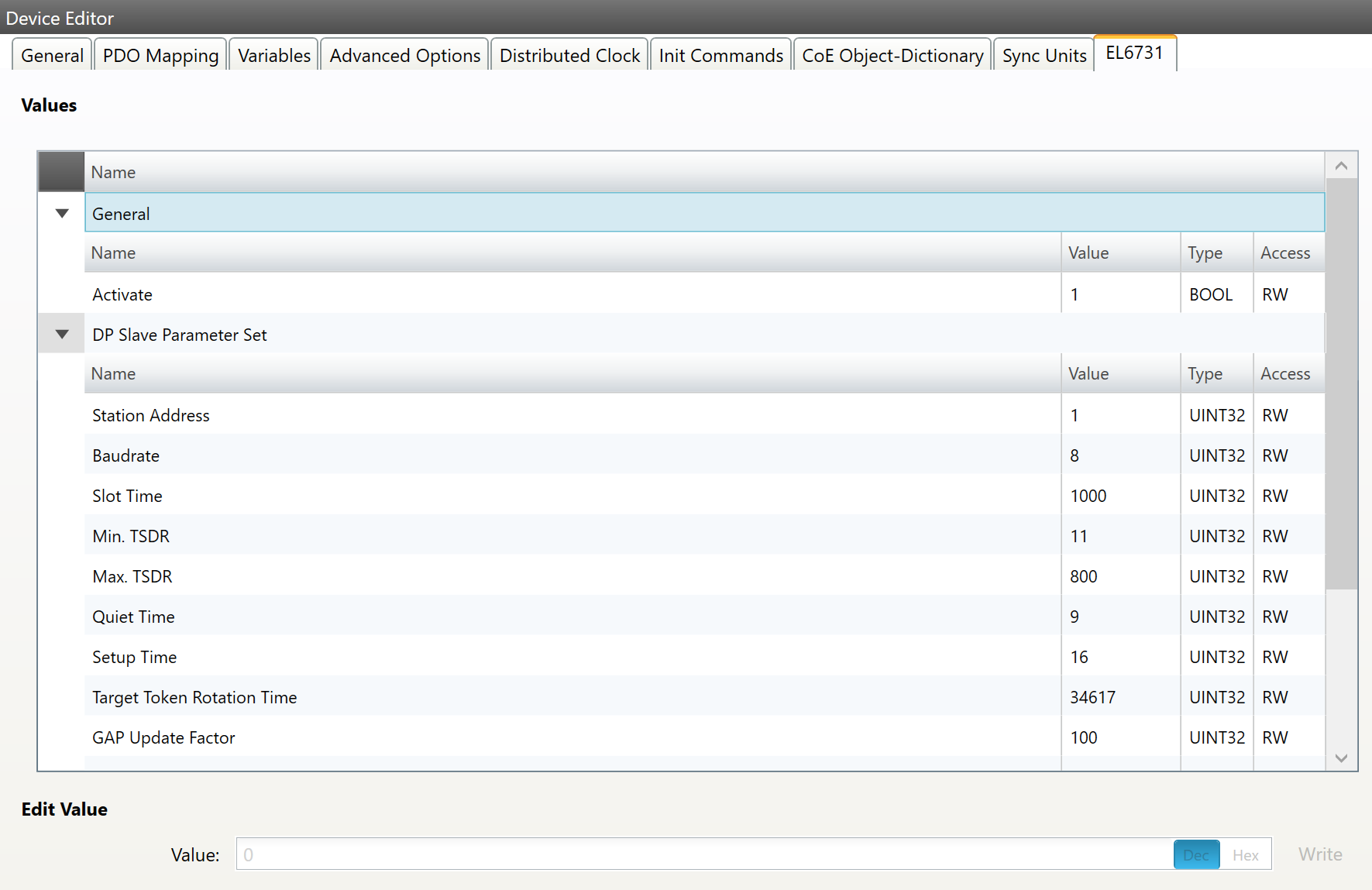
Each module has an own EL6731 tab with settings and the possibility to load a GSD file. After the GSD file was loaded the user gets also PRM data settings and the possibility to add a submodule (e.g. K-Bus) via the tree.
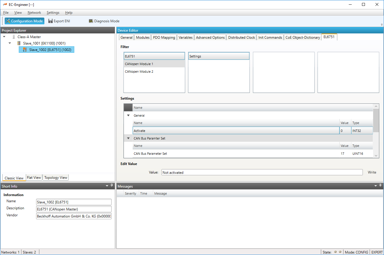
5.3.17. CANopen Master (EL6751)
In this tab, the user can configure the CANopen Master EL6751. He can add Modules, PDOs, SDOs and variables by clicking the right mouse button. To activate the master, the user have to go to the general settings of the EL6751 entry, and set activated to ‘1’. If activated is ‘1’ all init commands and PDOs will be activated automatically.
- Also the user can rename and delete modules, PDOs, SDOs, and variables:
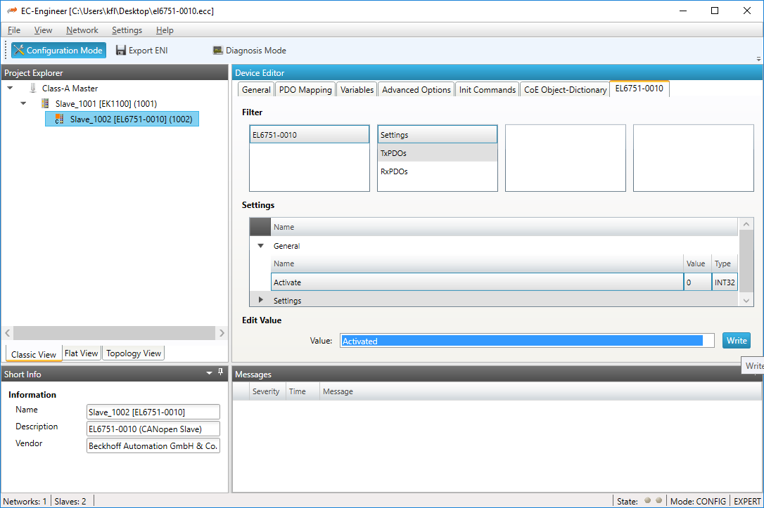
5.3.18. CANopen Slave (EL6751-0010)
In this tab, the user can configure the CANopen Slave EL675-0010. He can add PDOs and variables by clicking the right mouse button. To activate the gateway, the user have to go to the general settings of the EL6751-0010 entry, and set activated to ‘1’. If activated is ‘1’ all init commands and PDOs will be activated automatically.
- Also the user can rename and delete PDOs and variables:
5.3.19. Motion (Motion Mode only)
- On this tab the user can change the and activate the axis for the motion. The settings are used in the
xmlfile which can be exported from the master motion tab, to configure the Demo Motion: 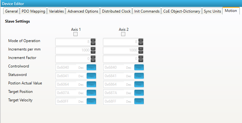
5.3.20. Simulation Settings
- On this tab the user can change the simulator settings for the slave:
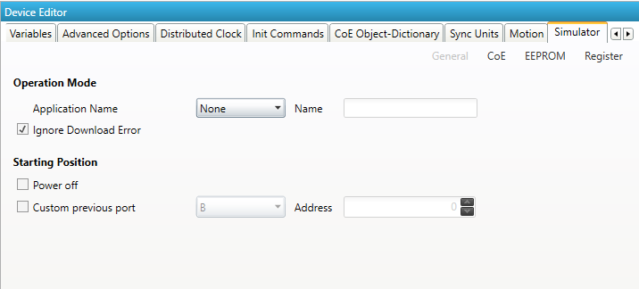
- Application Name:
The application name for the
EXIfile- Ignore Download Error:
Ignores errors on download
- Starting Position
- Power Off:
Select if slave should be powered on or off on start
- Custom previous port:
manipulate the topology
- CoE Tab
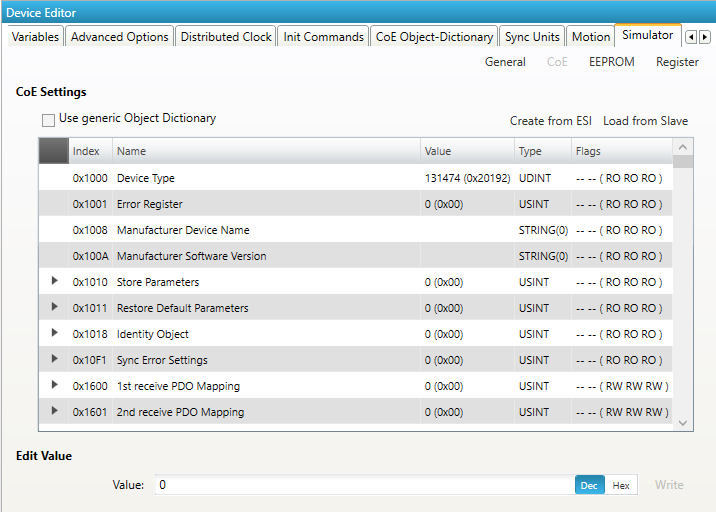
The simulated CoE can be changed here.
- EEPROM Tab
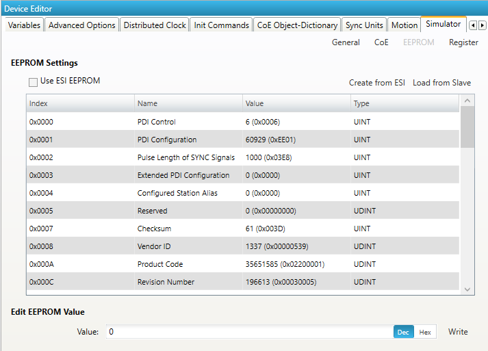
The simulated EEPROM can be changed here.
- Register Tab
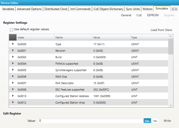
The simulated Registers can be changed here.
5.4. Export ENI
To run the EC-Master you basically need an EtherCAT-Network-Information (ENI) file to initialize and control an EtherCAT network. After configuring the EtherCAT network with EC-Engineer, you can export this ENI file and copy it on the control system to run the EC-Master.
Note
The EtherCAT-Network-Information (ENI) File will be generated according to ETG.2100 standard V1.0.1
5.5. Export EXI
To run the EC-Simulator you basically need an ENI or better an EXI file to simulate an EtherCAT network. After configuring the EtherCAT network with EC-Engineer, you can export this EXI file and use it to start the EC-Simulator.