4. Graphical user interface
4.1. Overview
- This section gives an overview about the graphical user interface:
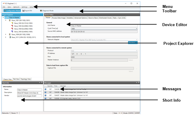
- The graphical user interface is divided into five parts:
- Menu/Tool/Status bar:
Shows current status or mode of the EC-Engineer and allows the user to change it.
- Project Explorer:
Shows different views of the current network configuration and allows the user to change it by adding or removing devices/slaves/modules.
- Device Editor:
Show information about the selected device, like process variables or PDO mappings. It allows the user also change this information.
- Short Info:
Show short information about selected device, like name, description or vendor.
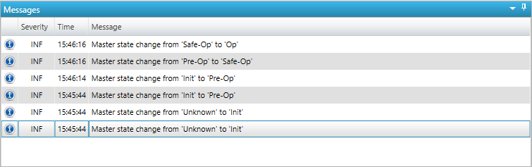
- Messages:
Shows notifications which occur e.g. when the EtherCAT Master has changed its operation state or a slave has been removed from (or added to) the EtherCAT network.
4.3. Project Explorer
4.3.1. Configuration Mode
There are three topology visualisation views:
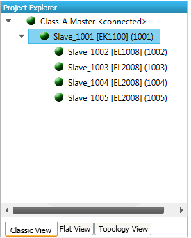
- Classic View
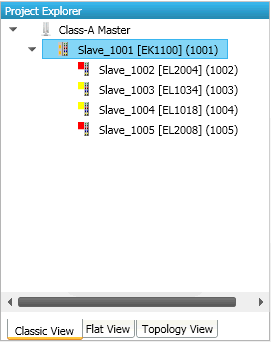
This is a tree view which has two levels. In the first level you can find coupler slaves or MDP slaves and in the second level you will see the connected slaves/modules.
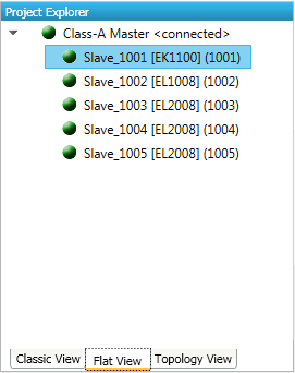
- Flat View
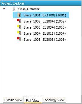
This view shows all slaves in a flat list, as they are connected in the EtherCAT network.
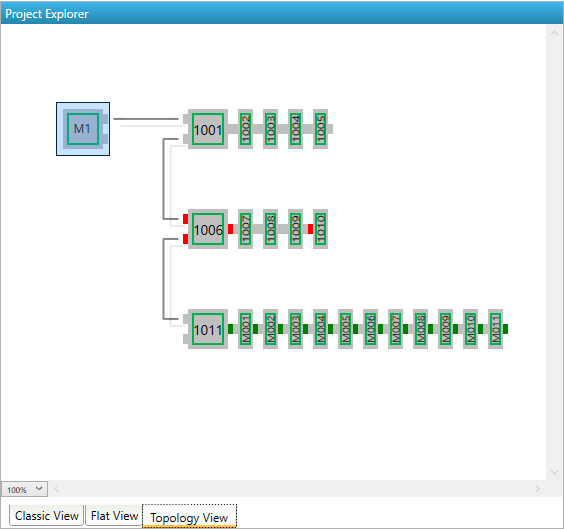
- Topology View
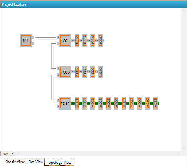
This view shows a graphical tree of all slaves, as they are connected in the EtherCAT network.
- The context menu of one or more selected slaves has the following entries:
- Append Slaves:
Appends a new slaves
- Remove Slaves:
Deletes the selected slaves
- Cut/Copy/Paste:
Extended clipboard operations, which should help the user to move or multiply existing slave definitions.
- Enable Slaves:
Appends disabled slaves to the process image at the previous position. If this is not possible, the slave will be marked as “not connected” and the user can append the slave by using “cut” & “paste”.
- Disable Slaves:
Removes the slaves from process image and from the exported
ENIfile, but keeps the slave as “disabled” in the project.- Reload ESI data:
Reloads
ESIdata which are stored in the project file from globalESIcache (after adding a slave to the project theESIdata will be stored in the project file).- Export SCI:
Exports a
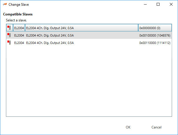
SCIfile. A SCI file is like an ESI file but preconfigured. So it is possible to create a fixed slave which can be added to the configuration and is working out of the box.- Change Slave:
Opens the following dialog, where the user can select a compatible slave (this is helpful, if the user wants to update the slave to a new revision and keeps his configuration). This is also used to change from an ESI to a SCI file.
- Import Beckhoff Slave Description, to import slave settings from TwinCAT (or ET9000)
- Import slave settings from “Beckhoff Slave Description” files
Open project in TwinCAT
Select slave to export
Main menu “TwinCAT”
Selected Item
Export
XMLDescriptionImport the exported file (imported will be MDP configuration, PDOs, DC settings, …)
- Import init commands of slave from “Beckhoff Init Command Description” files
Open project in TwinCAT
Select slave to export
Open tab “Startup”
Context menu: “Export to
XML”Import the exported file (imported will be the exported init commands)
- If user tries to append slave he will see the following dialog:
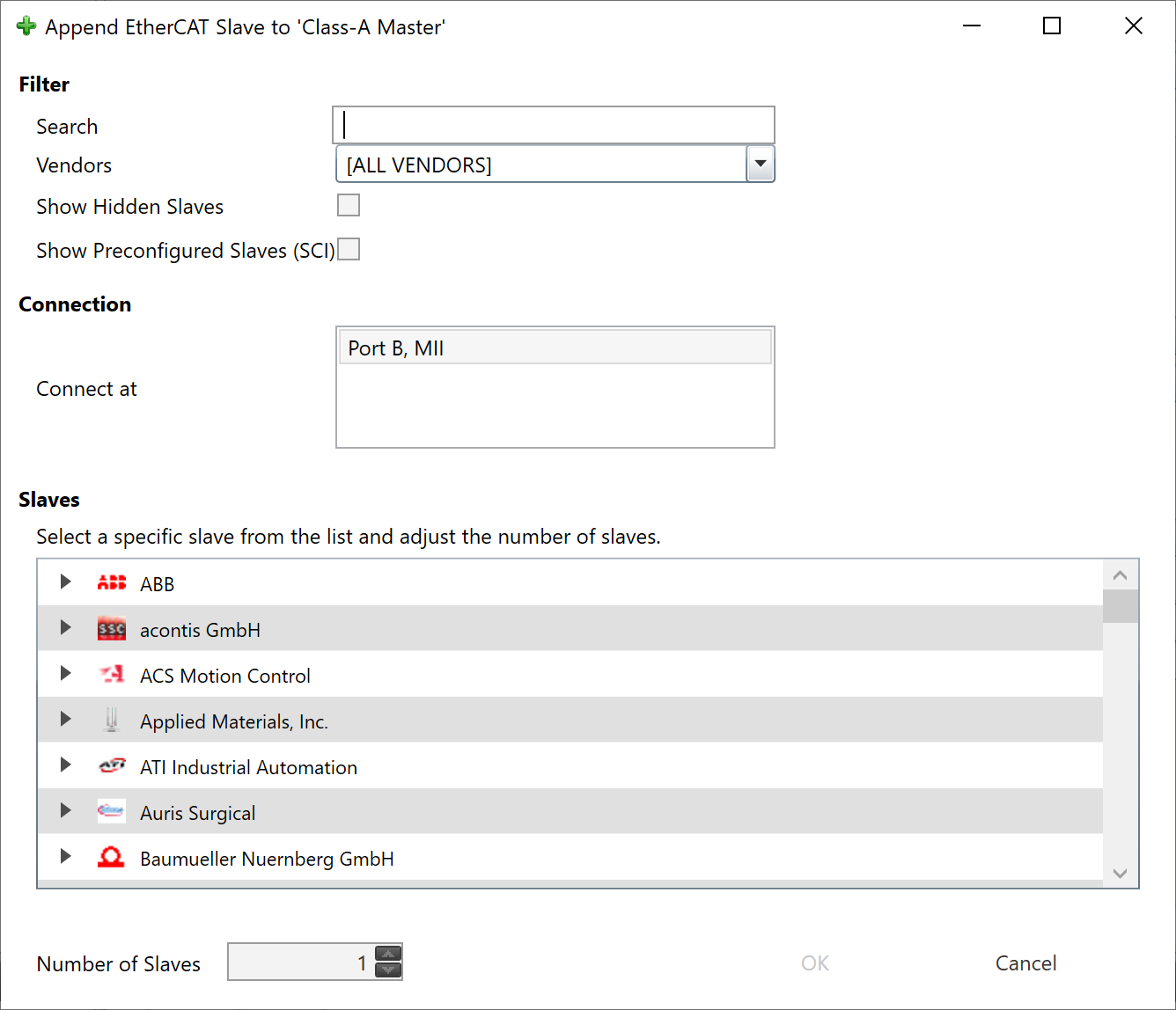
- Filter
Search: Keyword to filter the slaves by type name. Vendors: List of all available vendors. User can filter all slaves by selecting the desired vendor from the list. If it makes sense, the recommended vendor is already preselected, e.g. if you try to append a slave to an E-Bus. Show Hidden Slaves: Shows also hidden slaves (e.g. with older revisions, if newer slaves are available) Show Preconfiguren Slaves: Shows also slaves from SCI files
- Connection
Select the port where the predecessor device is connected (see General).
- List of available slaves
User can select the slave which he wants, be expanding the three levels: vendors, groups and the slaves themselves. The 3rd level consists of three parts: Type name, description and the revision number.
- Number of slaves
User can change this value if he wants to add more than one slave of the same type.
4.3.2. Diagnosis Mode
There are three topology visualisation views:
- Classic View
This is a tree view which has two levels. In the first level you can find coupler slaves and in the second level you will see the connected slaves.
- Possible device states:
 Init Bootstrap
 Pre-Op
 Safe-Op
 Op
Op
- Flat View
This view shows all slaves in a flat list, as they are connected in the EtherCAT network.
- Possible device states:
- Init Bootstrap Pre-Op Safe-Op Op
- Topology View
This view shows a graphical tree of all slaves, as they are connected in the EtherCAT network.
- Possible device states:
- Init Bootstrap Pre-Op Safe-Op Op
- Possible port states:
- Bad Cable Quality Constricted Cable Quality
 Good Cable Quality
If cable quality is constricted or bad, please check the error counters of the slave (for more information about the extended diagnosis, see Extended Diagnosis (Expert)).
4.4. Device Editor
- This Editor gives the user the possibility to read and write information of the selected master or slave:
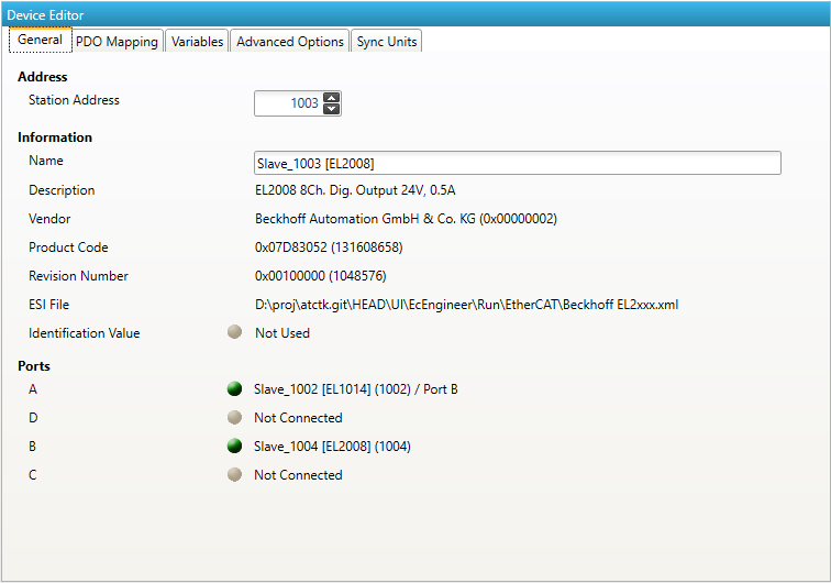
Some tabs in the Device Editor are Expert Settings. The menu item enables or disables the Expert Settings’ visibilty. Some tabs appear when configuring the first Slave.
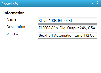
4.5. Short Info
- This window shows short information about selected device, like name, description or vendor:
4.6. Message Window
- Shows notifications which occur e.g. when the EtherCAT Master has changed its operation state or a slave has been removed from (or added to) the EtherCAT network: