2.1. Technical overview
2.1.1. DCM Modes
The following DCM Modes are available:
Name |
Purpose |
|---|---|
BusShift |
Synchronize slaves to master timer (Default) |
MasterShift |
Synchronize master timer to slave. Feasibility depending on target HW and SW. |
LinkLayerRefClock |
Bus Shift using Link Layer clock. Special HW needed. |
MasterRefClock |
Bus Shift excluding reference clock controlling. Lowers CPU usages, but very high timer accuracy needed. |
DCX |
Synchronization of two or more EtherCAT segments by a a bridge device. Only available with Feature Pack External Synchronization. |
See also
2.1.2. Sync signal activation
The sync signals are activated during transition PREOP - SAFEOP according to Init Command (Ado 0x0980, 0x0990, 0x09A0, 0x09A8).
2.1.3. DCM in sync
DCM in sync means that the synchronization between the send time of the cyclic frames and the system time of the reference clock was successful.
The master awaits that DCM is in sync in Master state transition PREOP->SAFEOP. Therefore the master state transition may timeout if DCM does not get in sync. Due to the Master’s DC implementation, DCM may get in sync in transition INIT->PREOP.
In sync is assumed if there is no error reported from the DCM controller within the settle time or if there is no DC slave connected.
2.1.4. Controller adjustment
To adjust the controller parameters the diagnostic values in file dcmlog0.0.csv can be used.
The generation of logging information can be enabled setting bLogEnabled to EC_TRUE with the function emDcmConfigure()
Controller log file description:
Column name |
Description |
|---|---|
Time[ms] |
Controller execution timestamp |
SyncSetVal [ns] |
Controller set value (distance between frame send time and SYNC0) |
BusTime [ns] |
System Time |
BusTimeOff |
System Time modulo Sync Cycle Time |
CtlAdj [ns] |
Controller adjust value |
CtlErr [ns] |
Controller error (EC_T_DCM_SYNC_NTFY_DESC.nCtlErrorNsecCur) |
CtlErrFilt |
Filtered controller error |
Drift [ppm] |
Drift between local clock and DC reference clock |
CtlErr [1/10 pmil] |
|
CtlOutSum |
|
CtlOutTot |
|
DCStartTime |
DC start time send to the slaves to activate their SYNC signals |
DCMErrorCode |
Current error code of the DCM controller (same value as returned by emDcmGetStatus) |
DCMInSync |
Current InSync state of the DCM controller |
DCInSync |
Current InSync state of the DC slaves |
SystemTimeDifference [ns] |
Current system time difference of the DC slave if monitoring is enabled |
Log file analyze: To understand how the controller values correlates the following table can helps.
Controller error |
Drift |
Reference-Clock |
Output |
|---|---|---|---|
Positive |
Must decrease |
Must run faster |
Double cycle time |
Negative |
Must increase |
Must run slower |
Half cycle time |
The DCM Controller reacts if the controller error is positive or negative. E.g. on a positive controller error (CtlErr ) the drift is too high and has to be decreased. Therefore the controller will speed up the reference clock.
In some case the drift is too high (EcMasterDemoDc shows error messages) and cannot be balanced by the controller. This holds if the drift is higher than about 400ppm.
Diagram 1: Bus offset in nanoseconds
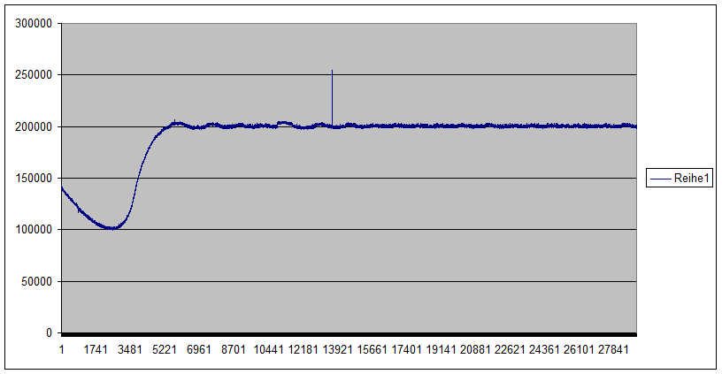
Diagram 2: Drift in ppm (part per million)
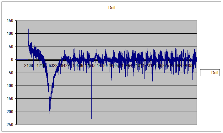
Diagram 3: Controller error in nanoseconds
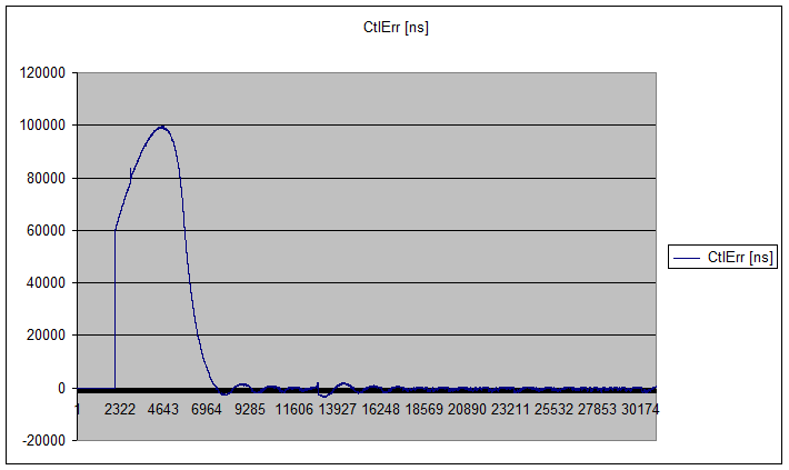
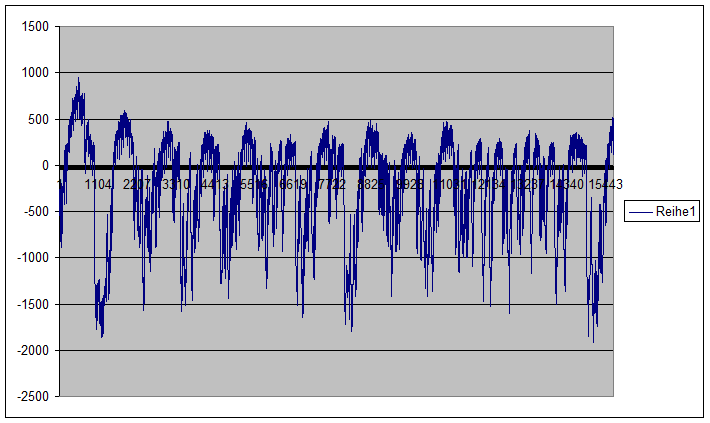
Diagram 4: Controller error in steady state in nanoseconds
Troubleshooting:
DCM BusShift needs a very deterministic and accurate time base.
The following statements have to be true:
The timer input frequency must be determined with an accuracy greater than 600 ppm (333333 Hz vs 333000 Hz. E.g. at 1 ms, the cycle time must be between 999.400 µs and 1000.600 µs)
The timer frequency must never change after the application start
On a PC platform the following settings have to be disabled in the BIOS. Be sure that these settings are really applied.
System management interrupt
Legacy USB support
Intel C-STATE tech
Intel Speedstep tech
Spread Spectrum
2.1.5. DCM Master Shift mode
In this mode, the local time base will be adjusted to synchronize it with the network “bus time”. The following function pointers have to be implemented to enable the adjustment:
EC_T_OS_PARMS::pfHwTimerGetInputFrequency
EC_T_OS_PARMS::pfHwTimerModifyInitialCount
The master shift must not be enabled in the ENI file because it doesn’t need any cyclic command. This mode can be activate using emDcmConfigure()
2.1.6. DCM Master Ref Clock mode
The DCM Master Ref Clock mode is similar to the bus shift mode, without its control loop. This reduces the CPU load and makes it a good alternative for low performance CPU. Because of the missing control loop, the reaction time on disturbance is longer and the cycle must be very accurate.
The bus shift time must be enabled in the ENI file because it use the same cyclic command to synchronize the EtherCAT network with master system
This mode can be activate using emDcmConfigure()
2.1.7. DCM Linklayer Ref Clock mode
In this mode the link layer should provide the time base for the cyclic frames. EC_LINKIOCTL_GETTIME will be called during the DC initialization to initialize the DC related registers of the DC slaves and during the slave transition PREOP to SAFEOP to start the DC SYNC signals if needed.
EC_LINKIOCTL_GETTIME should return the current 64 bits value in nanosecond of a time counter running continuously.
During the call to EcLinkSendFrame, the link layer should insert the send time of the frame following the instruction given by EC_T_LINK_FRAMEDESC::wTimestampOffset and EC_T_LINK_FRAMEDESC::wTimestampSize of the parameter pLinkFrameDesc. A value of 0 means that no time stamp should be inserted.