4. Configuration Mode
4.1. Overview
The EC-Master needs the EtherCAT-Network-Information ENI file to initialize and control the EtherCAT network.
In most cases the automatically generated Slave settings can be used to run the EtherCAT network.
In this chapter you can read how EC-EngineerWeb helps you to view or adjust those settings.
4.2. Master Settings
This section includes network related or master related settings. Some of those settings will also affect the “Master” section of the ENI.
4.2.1. Master
- In this tab, the user can configure the name of the master and the cycle time. If he wants to connect to a control system, this can be also configured.
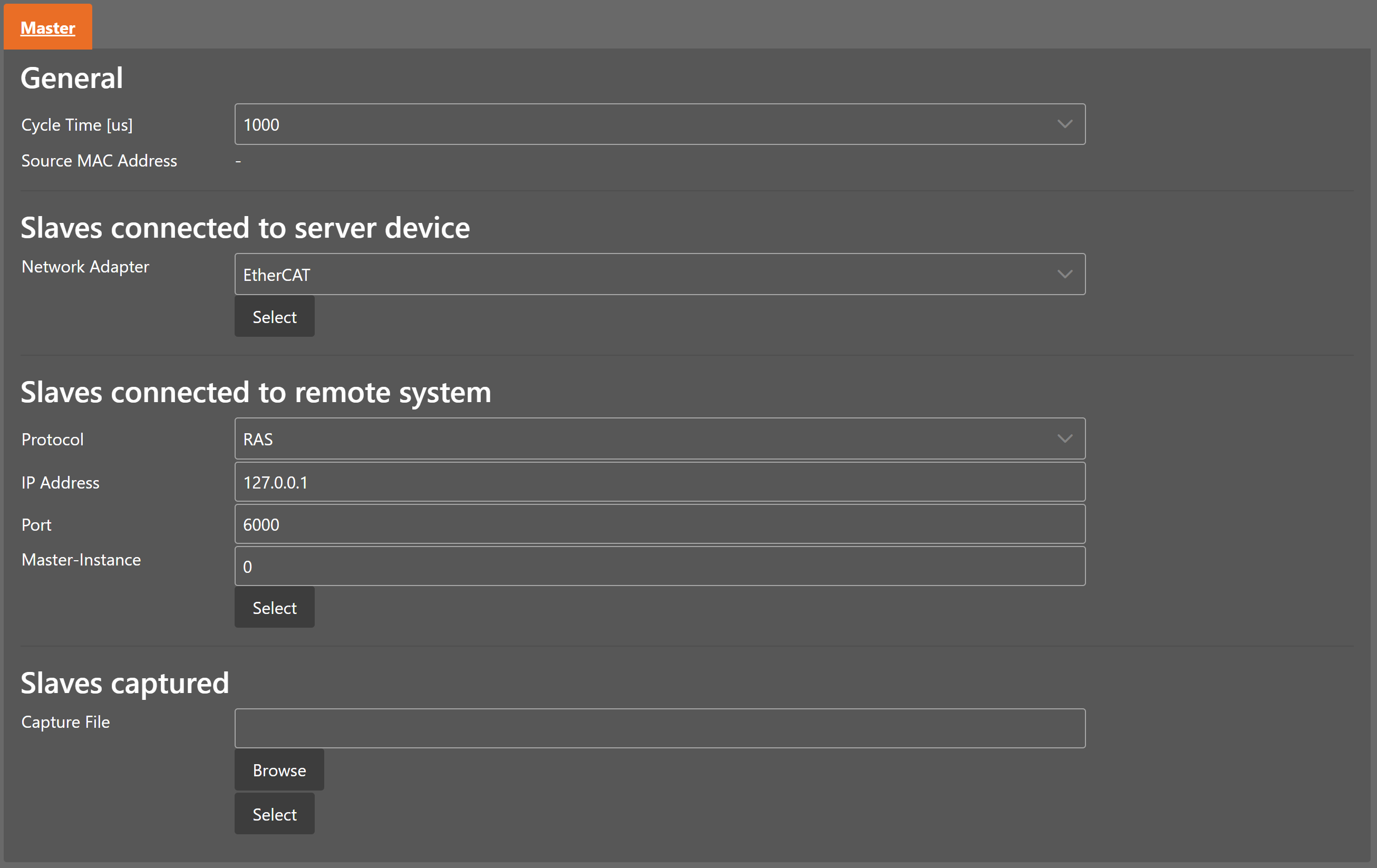
- General
- Cycle Time:
Interval in microseconds in which all EtherCAT commands will be sent from the master. The user can choose between the following values: 125, 250, 500, 1000, 2000 and 4000.
- Source MAC address:
MAC address of the connected system (will be filled during bus scan)
- Slaves connected to local system
- Network Adapter:
Network adapter which is connected to the control system
- Slaves connected to remote system
- Protocol:
Protocol of the remote system (e.g. RAS or Mailbox Gateway)
- IP Address:
IP address of the remote system, which is connected to the control system
- Port:
Port of the remote system, which is connected to the control system
- Master-Instance:
Used to determine which master instance should be used in the remote system (Master supports up to 10 instances).
- Slaves captured
- Capture File:
Capture file that should be started
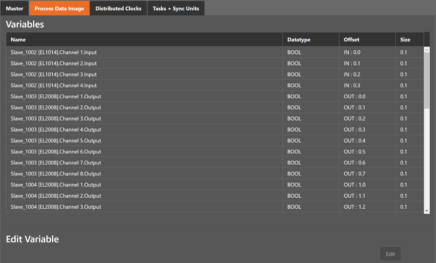
4.2.2. Process Data Image
- In this tab, the user can see all variables of the process data image and also edit the variable names.
4.2.3. Distributed Clocks
- In this tab, the user can change distributed clock related settings:
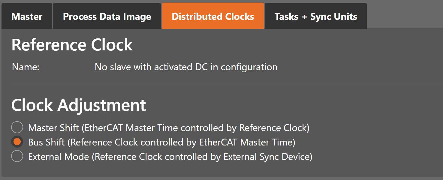
- Reference Clock
- Name:
Name of the reference clock. By default, this is the first slave with DC support.
- Clock Adjustment
- Master Shift:
The reference clock controls the Master time
- Bus Shift:
The Master time controls the reference clock
- External Mode:
The reference clock is controlled by an external sync device
4.2.4. Tasks and Sync Units
- In this tab, the user can define additional cyclic tasks and master sync units. After adding a new master sync unit, the user can assign one or more slave sync units on tab “Slave Sync Units” to this master sync unit.
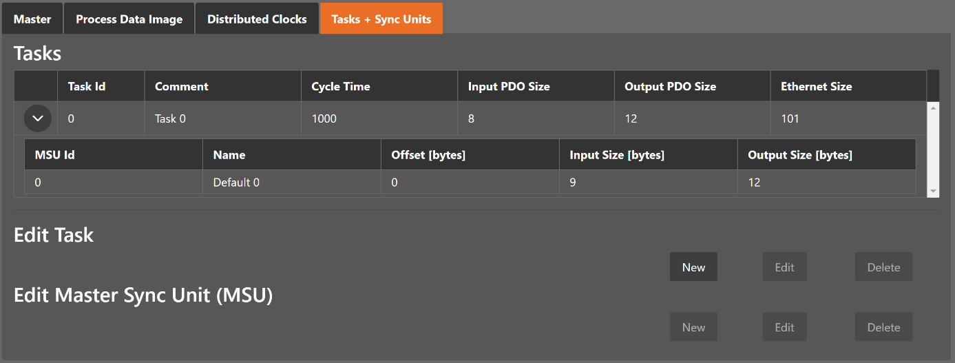
- Tasks
List of cyclic tasks and master sync units.
- Buttons
- New/Edit/Delete:
Used for changing the list.
- External Mode:
The reference clock is controlled by an external sync device
- If user wants to edit a task, he will see the following dialog:
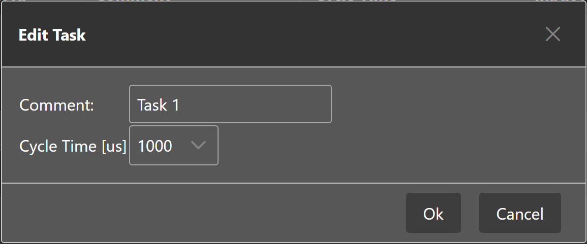
- Comment
Comment of this task (will be written to
ENIfile)- Cycle Time
Cycle time of this task
- If user wants to edit a master sync unit, he will see the following dialog:
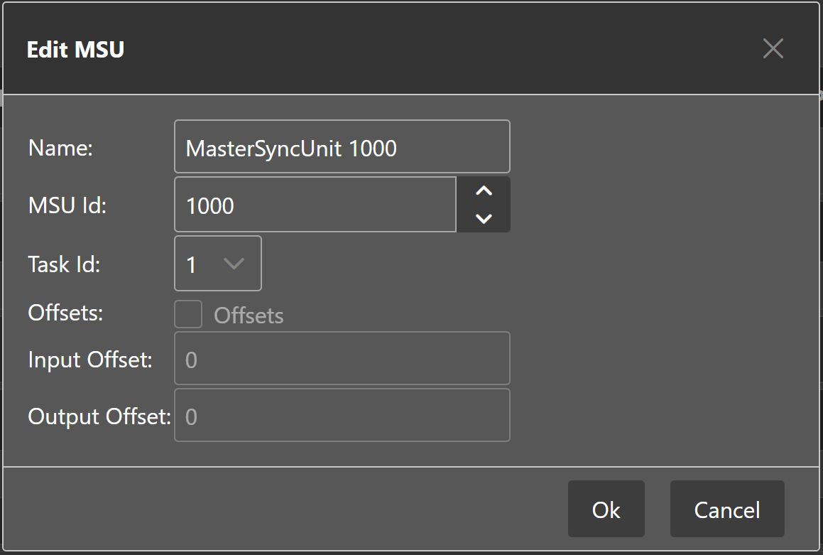
- Name
Name of this master sync unit (will be written to
ENIfile)- Sync Unit Id
- Id of this master sync unit (will be written to
ENIfile). - ID 0 .. 9:
Generated / internal master sync unit
- ID 10 .. 999:
Generated / internal master sync unit for groups
- ID 1000 .. 2000:
User defined master sync unit
- Id of this master sync unit (will be written to
- Task Id
Task Id to which is this master sync unit assigned
- Offsets
Activate to pin this master sync unit to a specific offset
- Input
Input offset of pinned master sync unit
- Output
Output offset of pinned master sync unit
4.3. Slave Settings
This section includes slave related settings. The most of all settings will affect the “Slave” section of the ENI.
4.3.1. General
- In this tab, the user can change general slave settings like station address or the name of the slave. He has also the possibility to change his predecessor device.
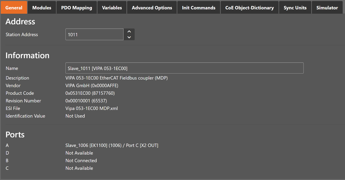
- Address
- Station Address:
Station address of the slave. By default, the first station address is 1001.
- Information
- Name:
Name of the slave. By default the following format is used “Slave_N [TYPE]”.
- Description:
Description of the slave (Read from
ESIfile)- Vendor:
Name of the vendor the slave
- Product Code:
Product Code of the slave
- Revision Number:
Revision Number of the slave
- ESI File:
Name of the
ESIfile where the description of the slave is stored.ESIfiles can be managed by using the ESI-Manager- Identification Value:
Identification Value of the slave
- Ports
- Connected Devices:
List of connected devices
- Predecessor Device:
Name of the predecessor device. If topology should be changed, please use the Edit Topology dialog
4.3.2. Modules
- In this tab, the user has can assign modules into the specific slots. He can also change the setting for downloading the slot configuration to the slave.
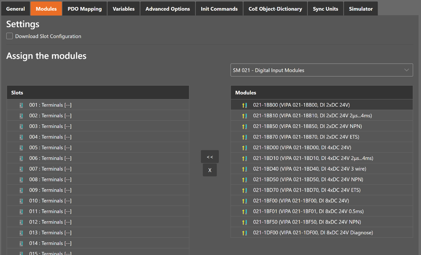
- Connect module to slot (“<<”)
Used for connecting the selected module (from the right list) to the selected slot (from the left list). If the slot is already connected, the module will be inserted and the subsequent modules will be moved (if this is supported from the slave)
- Disconnect module from slot (“X”)
Used for disconnecting the selected slot (left list)
4.3.3. PDO Mapping
- In this tab, the user can see the current PDO mappings. For some Slave types the user can activate or deactivate some PDO configurations.
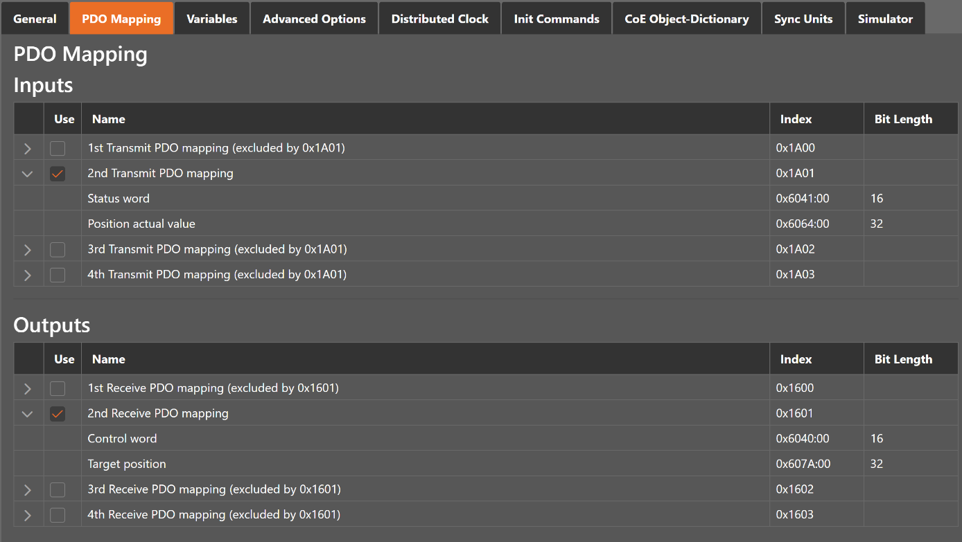
- Lists of inputs or outputs
- Checkbox:
Signals if PDO will be used for the current configuration or not.
4.3.4. Variables
- In this tab, the user can see the variables of the slave and if it is allowed he can also edit variables
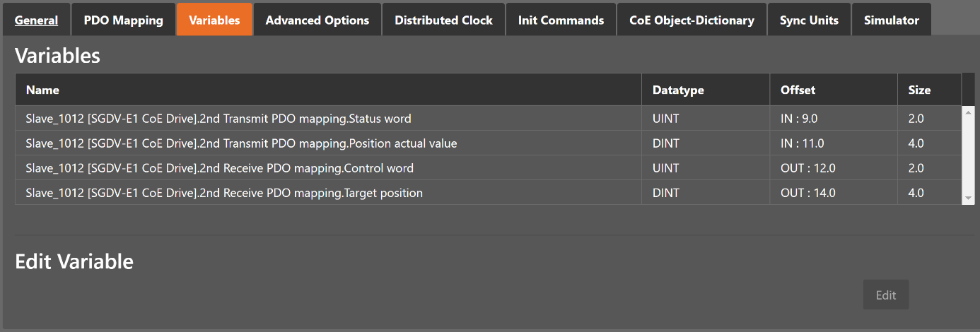
- Lists of Variables
Variables comes from the
ESIfile or will be generated from the configurator.
4.3.5. Advanced Options
- In this tab, the user can change advanced options of the slave.
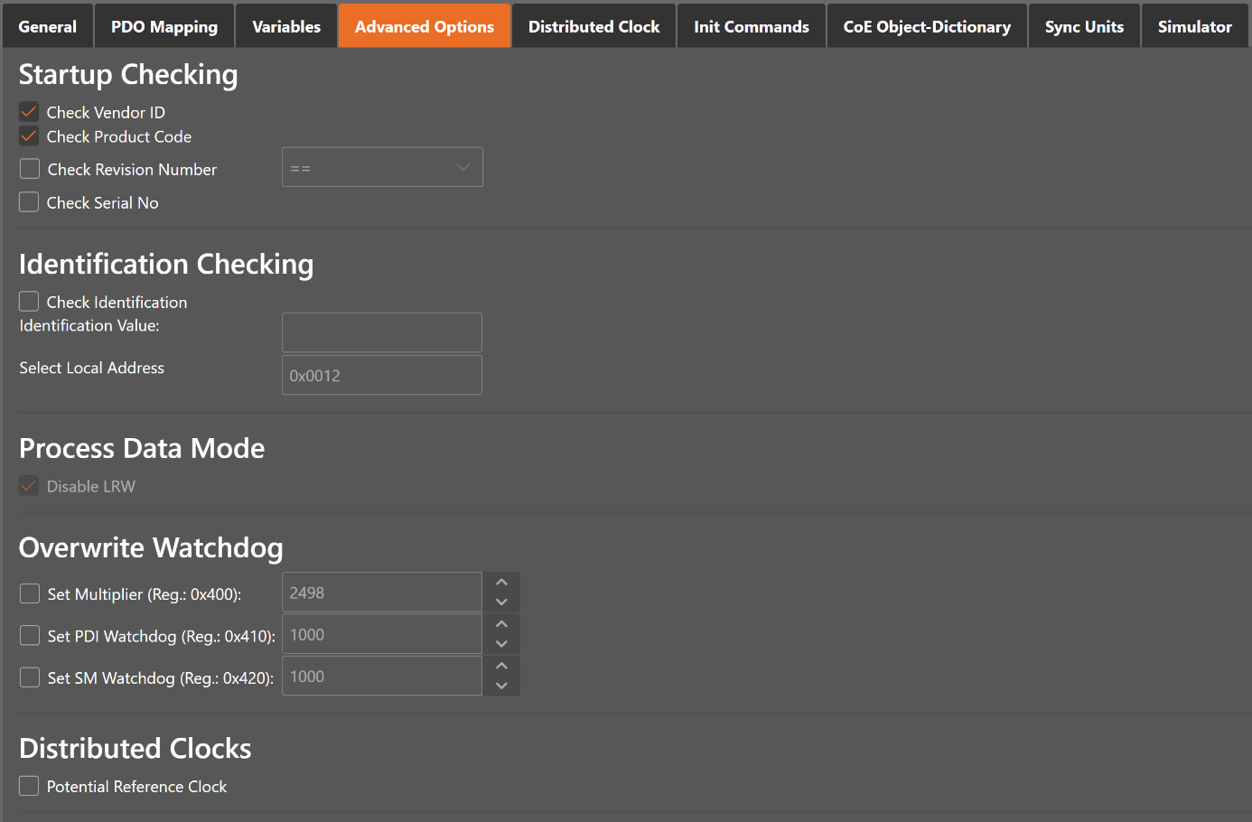
- Startup Checking
Master will check the Vendor ID, Product code, Revision number if the state machine changes from INIT to PREOP of the slave
- Revision number can be verified by six ways:
“==” HI word is equal, LO word is equal
“>=” HI word is equal or greater, LO word is equal or greater
“LW ==” HI word is equal
“LW ==, HW >=” LO word is equal, HI word is equal or greater
“HW ==” LO word is equal
“HW ==, LW >=” HI word is equal, LO word is equal or greater
- Identification Checking
If Check Identification is selected, the Identification Value of the slave is checked. In the Box is the register of the Identification Value.
- Process Data Mode
- Disable LRW:
Determines whether LRD/LWR command or the LRW command is used for accessing process data. Cable redundancy needs LRD/LWR, Slave-to-slave-copy needs LRW.
- Watchdog
- Set Multiplier:
Writes the configured value to the corresponding slave register: 0x0400
- Set PDI Watchdog:
Writes the configured value to the corresponding slave register: 0x0410 (0 = Watchdog is disabled)
- Set SM Watchdog:
Writes the configured value to the corresponding slave register: 0x0420 (0 = Watchdog is disabled)
- Distributed Clocks
- Potential Reference Clock: Set to use slave as a potential reference clock
This might be useful, if e.g. a hot connect slave, which is used as reference clock, was disconnected from the network
In that case the EC-Master searches for the first potential reference clock
If no potential reference clock slave was found, the first DC slave will be used
- Timeouts
- SDO Access:
Internal master timeout which is used for accessing the SDO (0 = Use internal default value of the master)
- InitPreOp:
Internal master timeout with is used for changing slave state
- Pre-OpSave-Op or Safe-OpOp:
Internal master timeout with is used for changing slave state
- Back to Pre-Op, Init:
Internal master timeout with is used for changing slave state
- OpSafe-Op:
Internal master timeout with is used for changing slave state
- Mailbox Mode
- Cyclic:
Interval in milliseconds within the input mailbox will be read (polling mode)
- State Change:
The input mailbox will be read only if the status bit is set
- Overwrite Mailbox Size
- Output Size:
Overwrites mailbox output size
- Input Size:
Overwrites mailbox input size
- Process Data Sync Manager Mode
- Default:
Uses sync manager mode from
ESIfile- Buffered (3 buffer mode):
Enables 3 buffer mode
- Mailbox (Single buffer mode):
Enables single buffer mode
4.3.6. Distributed Clocks (Slave)
- In this tab, the user can change distributed clock related settings.
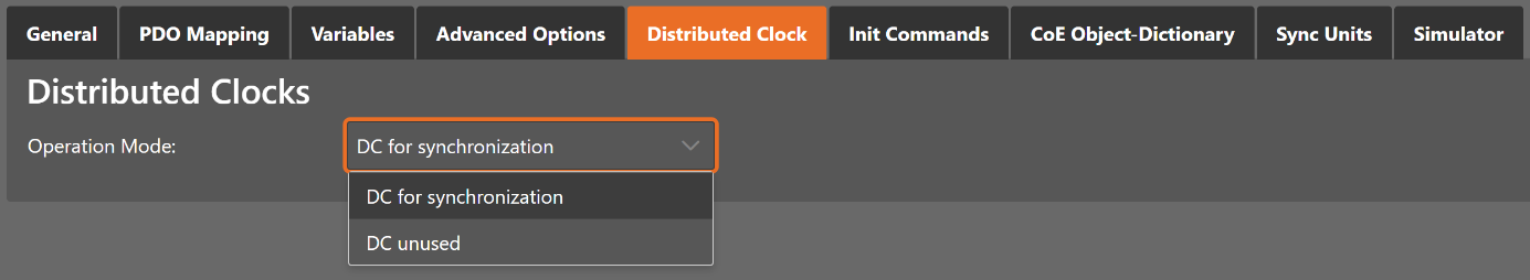
- Operation Mode:
Selectable DC operation modes. The modes cannot be edited.
4.3.7. Init Commands
- In this tab, the user can view the current configured init commands and if it is allowed he can also add/edit/delete init commands.
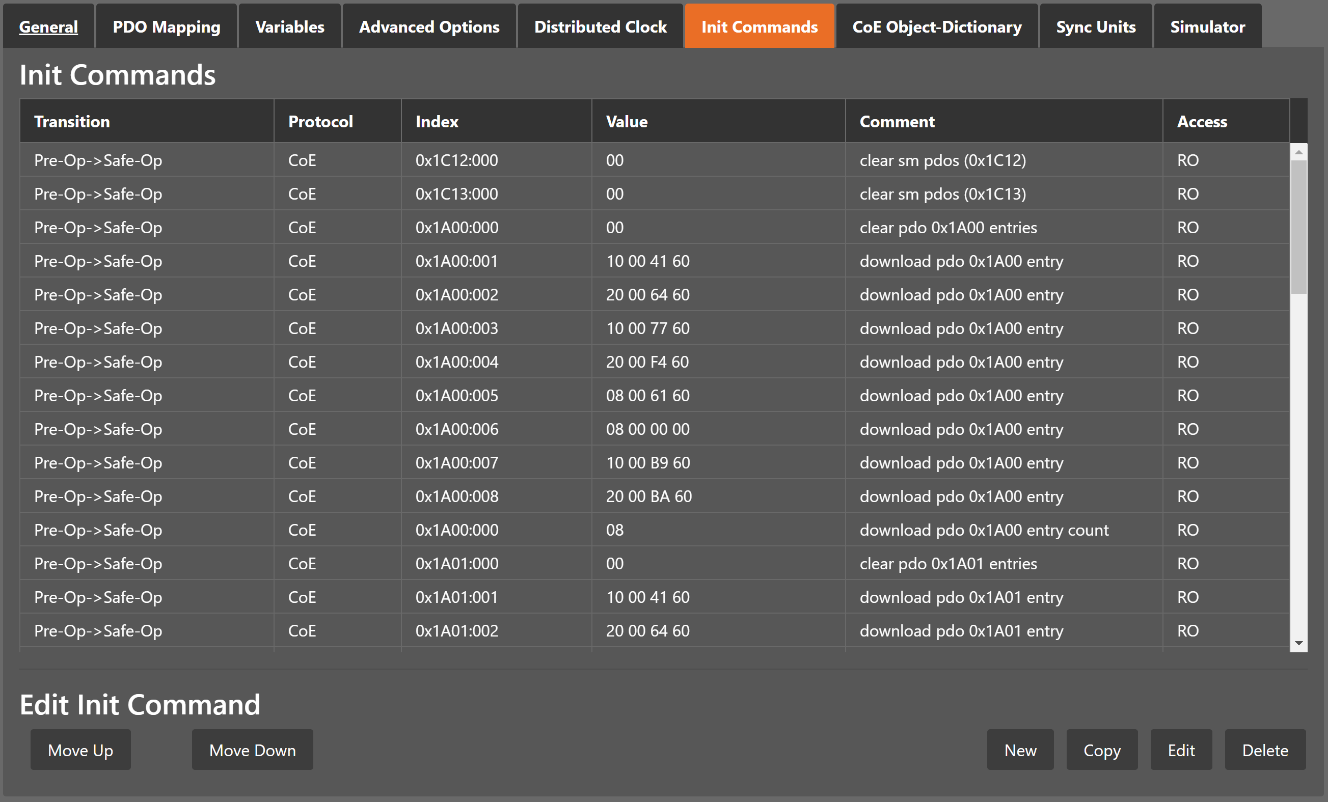
- Lists of Init Commands
Init Commands comes from the
ESIfile or will be generated from the configurator. The column tells the user if this Init Command can be edited (RW = Read/Write) or not (RO = Read-Only).- Buttons
- New/Copy/Edit/Delete:
Used for changing the list
- Up/Down:
Moving the selected Init Command up or down
- At the moment only Init Commands of the CoE- Protocol can be added or changed. If the user wants to do this he will see the following dialog (CoE):
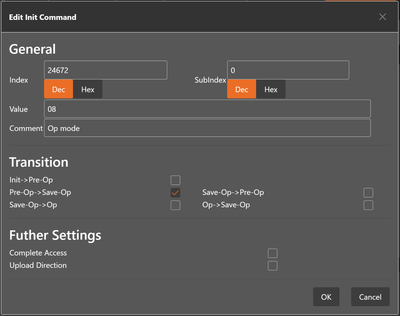
- General
- Index:
CoE-Index of the Init Command
- SubIndex:
CoE-SubIndex of the Init Command
- Value:
Value of the Init Command, which should be written in the chose transition (only available if direction is set to Download). If type of value is unknown, the hex format must be used like “00 11 22 33 …”.
- Comment:
Comment of the Init Command
- Transition
Determines in which transition the Init Command will be executed
- Further Settings
Determines if the complete SDO object should be written/read
- Direction
- Determines the direction of the Init Command
- Download:
Writes value to slave
- Upload:
Reads value from slave (e.g. necessary if value must be confirmed)
4.3.8. CoE Object-Dictionary
- In this tab, the user can see and edit the offline CoE object dictionary.
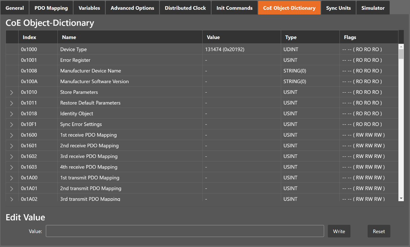
- Lists of CoE Object-Dictionary entries
Entries comes from the
ESIfile or will be generated from the configurator.- The column tells the user if this entry is an PDO entry and if it can be edited
“AA BB (CC DD EE)”
AA = Mapping as RX PDO or not
BB = Mapping as TX PDO or not
CC = Access rights for PreOp (RO, WO, RW)
DD = Access rights for SafeOp (RO, WO, RW)
EE = Access rights for Op (RO, WO, RW)
- Buttons
- Update:
Changes the selected entry
- Reset:
Resets the selected entry to
ESIdefault
4.3.9. Groups
- In this tab, the user can choose if this group has a fixed offset in the process data image or if this group is a hot connect group.
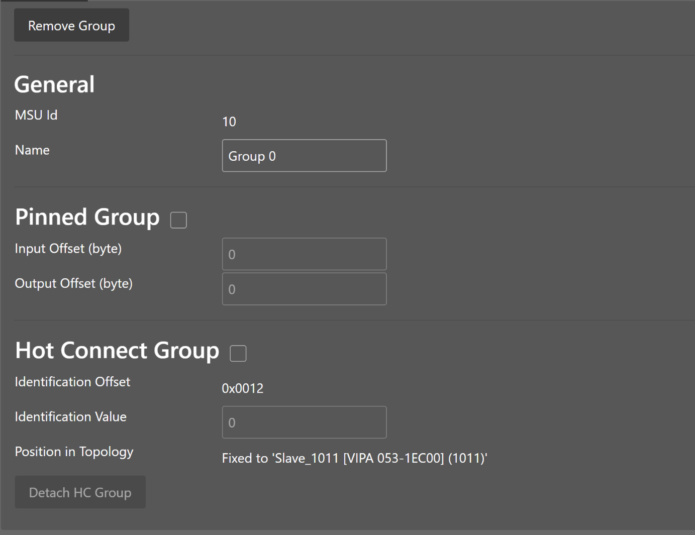
Note
Tab is only visible if slave is the first member of a group.
- General
- MSU Id:
Generated Master Sync Unit Id
- Name:
Name of the group
- Pinned Group
- Input Offset:
Fixed input offset of the group in the process data image in bytes
- Output Offset:
Fixed output offset of the group in the process data image in bytes
- Hot Connect Group
- Identification Offset:
Register offset where the identification can be read from the slave
- Identification Value:
Hardware identification value or configured station alias address can be used. For more information about the configured station alias address, EC-Engineer Chapter EEPROM.
A new group can be created by clicking Create Group in the toolbar. Select all slaves you like in the group and click Confirm in the toolbar. Now a group has been created. On the goup tab (first slave) are more settings like Hot Connect, Pinned Group and also remove the group or detach it.
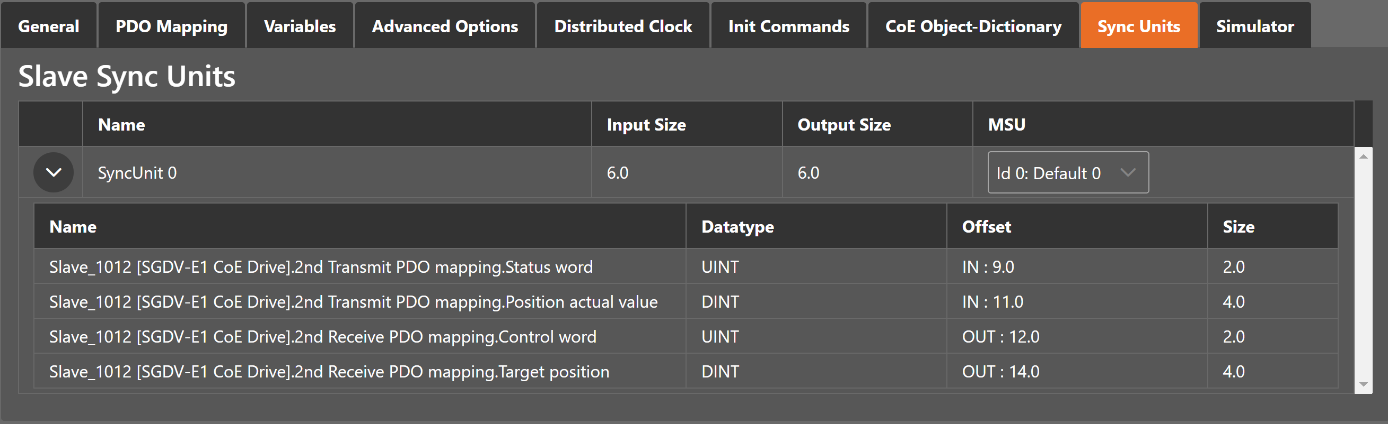
4.3.10. Sync Units
- In this tab, the user can assign a slave sync unit to a specific master sync unit by using the combobox column (only visible if user has defined additional master sync units).
4.4. Export ENI
To run the EC-Master you basically need an EtherCAT-Network-Information ENI file to initialize and control an EtherCAT network. After configuring the EtherCAT network with EC-Engineer, you can export this ENI file and copy it on the control system to run the EC-Master.
Note
The EtherCAT-Network-Information ENI File will be generated according to ETG.2100 standard V1.0.0
4.5. Export EXI
To run the EC-Simulator you basically need an ENI or better an EXI file to simulate an EtherCAT network. After configuring the EtherCAT network with EC-Engineer, you can export this EXI file and use it to start the EC-Simulator.
4.6. Export EBI
To run the EniBuilder you basically need an EBI file to create an ENI. After configuring the EtherCAT network with EC-Engineer, you can export this EBI file and use it to start the EniBuilder.