Skip to content
EC-Simulator 3.1 documentation logo
EC-Simulator 5.1. Link Layer initialization
Type to start searching
    • | EtherCAT manuals |
    • | www.developer.acontis.com |
    • | www.acontis.com |
    • 5. Link Layer
    • 1. Introduction
      • 1.1. What is EtherCAT?
      • 1.2. EC-Simulator - Features
      • 1.3. Editions (HiL / SiL)
      • 1.4. Protected version
      • 1.5. Known restrictions
      • 1.6. License
    • 2. Getting Started
      • 2.1. EC-Simulator Architecture
      • 2.2. Extended EtherCAT Network Configuration (EXI)
      • 2.3. HiL Simulation Software architecture
      • 2.4. SiL Simulation Software architecture
      • 2.5. Mixed mode of real slaves and simulated slaves
      • 2.6. Operating system configuration
      • 2.7. Running EcSimulatorHilDemo
      • 2.8. Using emllSimulator (SiL)
      • 2.9. EC-Simulator Software Development Kit (SDK)
      • 2.10. Link Layer configuration for EcSimulatorHilDemo
    • 3. Software Integration
      • 3.1. EcSimulatorHilDemo
      • 3.2. Process data update and synchronization
      • 3.3. Accessing process data in the application
      • 3.4. Hot Connect
      • 3.5. Error detection and diagnosis
      • 3.6. RAS-Server for EC-Lyser and EC-Engineer
      • 3.7. EC-Simulator stack Source Code
      • 3.8. EcSimulatorHilDemoMotion
    • 4. Platform and Operating Systems (OS)
      • 4.1. tenAsys INtime
      • 4.2. Linux
      • 4.3. QNX Neutrino
      • 4.4. Windriver VxWorks
      • 4.5. Microsoft Windows
      • 4.6. Xenomai
    • 5. Link Layer
      • 5.1. Link Layer initialization
      • 5.2. Intel Pro/1000 - emllI8254x
      • 5.3. Intel Pro/100 - emllI8255x
      • 5.4. Broadcom BcmGenet - emllBcmGenet
      • 5.5. Beckhoff CCAT - emllCCAT
      • 5.6. Texas Instruments CPSW - emllCPSW
      • 5.7. DW3504 - emllDW3504
      • 5.8. Xilinx EMAC - emllEMAC
      • 5.9. Freescale TSEC / eTSEC - emllETSEC
      • 5.10. Freescale FslFec - emllFslFec
      • 5.11. Xilinx Zynq-7000/Ultrascale (GEM) - emllGEM
      • 5.12. Texas Instruments ICSS - emllICSS
      • 5.13. Windows NDIS - emllNdis
      • 5.14. Windows WinPcap - emllPcap
      • 5.15. RDC R6040 - emllR6040
      • 5.16. Realtek RTL8169 - emllRTL8169
      • 5.17. Renesas SHEth - emllSHEth
      • 5.18. VxWorks SNARF - emllSNARF
      • 5.19. Linux SockRaw - emllSockRaw
    • 6. Application programming interface, reference
      • 6.1. Generic API return status values
      • 6.2. Multiple EtherCAT Network Support
      • 6.3. General functions
      • 6.4. Process Data Access Functions
      • 6.5. Notifications
      • 6.6. esNotifyApp
      • 6.7. Network operation functions
      • 6.8. Error simulation functions
      • 6.9. Slave control and status functions
      • 6.10. ADS over EtherCAT (AoE)
      • 6.11. CAN application protocol over EtherCAT (CoE)
      • 6.12. Ethernet over EtherCAT (EoE)
      • 6.13. File access over EtherCAT (FoE)
      • 6.14. Vendor specific access over EtherCAT (VoE)
      • 6.15. Distributed Clocks (DC)
    • 7. Error Codes
      • 7.1. Groups
      • 7.2. Generic Error Codes
      • 7.3. DCM Error Codes
      • 7.4. ADS over EtherCAT (AoE) Error Codes
      • 7.5. CAN application protocol over EtherCAT (CoE) SDO Error Codes
      • 7.6. File Transfer over EtherCAT (FoE) Error Codes
      • 7.7. Servo Drive Profil over EtherCAT (SoE) Error Codes
      • 7.8. Remote API Error Codes

    5.1. Link Layer initialization

    The different Link Layer modules are selected and parameterized by a Link Layer specific structure. Each Link Layer specific structure start with a common EC_T_LINK_PARMS structure, followed by some Link Layer specific members. The common link parameter structure is passed to EC_T_INIT_SIMULATOR_PARMS::pLinkParms with the call of esInitSimulator() like in the following example:

    /* identify Link Layer in the common struture */
    oLinkParmsSockRaw.linkParms.dwSignature = EC_LINK_PARMS_SIGNATURE_SOCKRAW;
    oLinkParmsSockRaw.linkParms.dwSize = sizeof(EC_T_LINK_PARMS_SOCKRAW);
    OsStrncpy(&oLinkParmsSockRaw.linkParms.szDriverIdent, EC_LINK_PARMS_IDENT_SOCKRAW, EC_DRIVER_IDENT_MAXLEN);
    
    /* specific Link Layer parameters should be set here */
    
    /* pass Link Layer parameters */
    oInitMasterParms.dwSignature = ATECAT_SIGNATURE;
    oInitMasterParms.dwSize = sizeof(EC_T_INIT_MASTER_PARMS);
    oInitMasterParms.pLinkParms = &oLinkParmsSockRaw.linkParms;
    
    /* more parameters should be set here */
    
    /* initialize master */
    emInitMaster(dwInstanceId, &oInitMasterParms);
    
    struct EC_T_LINK_PARMS

    Public Members

    EC_T_DWORD dwSignature

    [in] Signature of the adapter specific structure containing the EC_T_LINK_PARMS structure

    EC_T_DWORD dwSize

    [in] Size of the adapter specific structure containing the EC_T_LINK_PARMS structure

    EC_T_LOG_PARMS LogParms

    [in] Logging parameters

    EC_T_CHAR szDriverIdent[EC_DRIVER_IDENT_NAMESIZE]

    [in] Name of Link Layer module (driver identification) for Link Layer Selection

    EC_T_DWORD dwInstance

    [in] Instance of the adapter. if EC_LINKUNIT_PCILOCATION is set: contains PCI address

    EC_T_LINKMODE eLinkMode

    [in] Mode of operation

    EC_T_CPUSET cpuIstCpuAffinityMask

    [in] Interrupt service thread CPU affinity mask

    EC_T_DWORD dwIstPriority

    [in] Task priority of the interrupt service task (not used in polling mode)

    enum EC_T_PHYINTERFACE

    Values:

    enumerator ePHY_UNDEFINED

    undefined

    enumerator ePHY_FIXED_LINK

    No PHY access at all

    enumerator ePHY_MII

    MII 10 / 100 MBit

    enumerator ePHY_RMII

    Reduced MII, 10 / 100 MBit

    enumerator ePHY_GMII

    Gigabit MII, 10, 100, 1000 MBit

    enumerator ePHY_SGMII

    Serial (SERDES) Gigabit MII, 10, 100, 1000 MBit

    enumerator ePHY_RGMII

    Reduced Gigabit MII, 10, 100, 1000 MBit

    enumerator ePHY_OSDRIVER

    Get interface type from OS

    enumerator ePHY_RMII_50MHZ

    ePHY_RMII with 50 MHz clock mode

    struct EC_T_LINK_TTS

    Public Members

    EC_T_BOOL bEnabled

    [in] Use Time-Triggered Send

    EC_T_DWORD dwCycleTimeUsec

    [in] Cycle time between 2 pfnStartCycle calls

    EC_T_DWORD dwSendOffsetUsec

    [in] Time between pfnStartCycle call and frame transmission

    EC_T_LINK_TTS_CALLBACK pfnStartCycle

    [in] Callback function called cyclically according dwCycleTimeUsec

    EC_T_VOID *pvStartCycleContext

    [in] Context passed to each pfnTtsStartCycle call

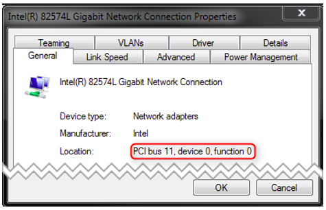
    5.1.1. Link Layer instance selection via PCI location

    For some operating systems it is possible to address the Link Layer instance using its PCI address as an alternative. To do this, EC_LINKUNIT_PCILOCATION (0x01000000) and the PCI location must be set as EC_T_LINK_PARMS::dwInstance.

    On Linux the PCI address can be shown using e.g.:

    lspci | grep Ethernet
    
    00:19.0 Ethernet controller: Intel Corporation Ethernet Connection I217-LM (rev 04)
    04:00.0 Ethernet controller: Intel Corporation 82574L Gigabit Network Connection
    05:00.0 Ethernet controller: Intel Corporation 82574L Gigabit Network Connection
    

    The format of EC_T_LINK_PARMS::dwInstance using PCI bus address is:

    0x01bbddff
    • bb Bus Number

    • dd Device Number

    • ff Function Number

    EC_T_LINK_PARMS::dwInstance = 0x01001900; //"0000:00:19.0"
    

    On Windows the integer value displayed in properties dialog must be converted to HEX. E.g the number from the following dialog (PCI bus 11, device 0, function 0) corresponds to 0x010B0000 (bus 0x0B).

    Previous 5. Link Layer
    Next 5.2. Intel Pro/1000 - emllI8254x
    © Copyright 2023-Sep-04, acontis technologies GmbH.
    Created using Sphinx 4.2.0. and Material for Sphinx