3. Software Integration
3.1. Network Timing
Interaction between application and EtherCAT network
EC-Master has no internal tasks, the operation is fully controlled by the user’s application. The benefits of this design are:
No synchronization issues between application and EC-Master
Consistent process data without using any locks
Various network timings driven by the application possible
Cyclic part may run within Interrupt Service Routine (ISR)
Easy to integrate
From the application perspective, EC-Master behaves like a driver that is controlled by the emExecJob() function with additional parameters, so-called EC_T_USER_JOB.
Typical sequence of EC_T_USER_JOB for emExecJob() to be called cyclically by the application:
 Refresh Inputs
EC_T_USER_JOB::eUsrJob_ProcessAllRxFrames: Process all received frames Write Outputs
EC_T_USER_JOB::eUsrJob_SendAllCycFrames: Send cyclic frames to update process output data. Administration
EC_T_USER_JOB::eUsrJob_MasterTimer: Trigger master and slave state machines. Send acyclic datagrams/commands
EC_T_USER_JOB::eUsrJob_SendAcycFrames: Transmit pending acyclic frame(s).
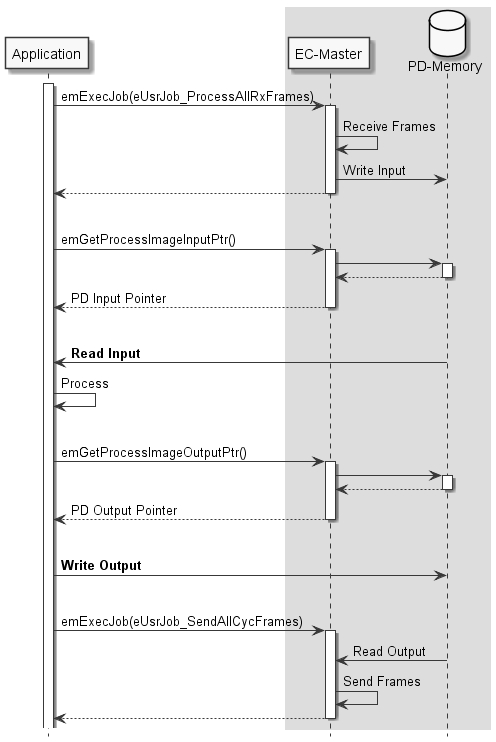
When a process data update is initiated by calling emExecJob(eUsrJob_ProcessAllRxFrames) new input data are read from the received frames and copied into the process data image. After the function returns the application can process the inputs, calculate the outputs and update the values in the process image. With calling emExecJob(eUsrJob_SendAllCycFrames) the output data are read from the process data image and stored in Ethernet/EtherCAT frames prior to sending them to the Link Layer. When this call returns all output process data values are stored in Ethernet/EtherCAT frames which are then processed by the network controller.
If only one single thread is both writing into the process data image and calling emExecJob(eUsrJob_SendAllCycFrames) no further output process data synchronization is necessary.
The application is responsible to (cyclically) calling the function emExecJob() with the appropriate parameters.
EtherCAT frames are divided into two categories:
- Cyclic frames
Contain process output and input data
Distributed Clocks (DC): Contain datagram to distribute network time
Typically sent by master in every cycle
Defined by the configuration tool (which data to read and to write)
- Acyclic frames
Asynchronous, event triggered communication
Mailbox communication (CoE, FoE, EoE)
Status requests (e. g. read slave state information)
Raw EtherCAT datagrams requested by application
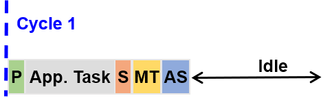
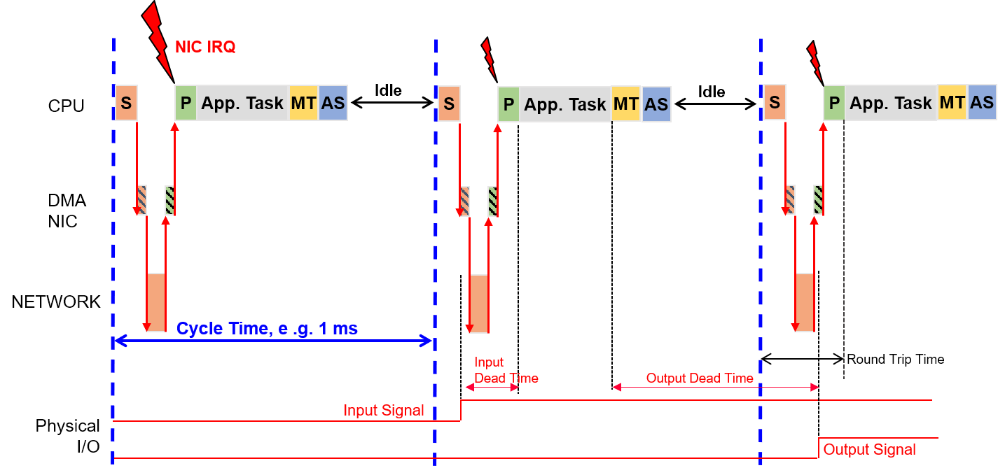
3.1.1. Standard Timing: Short output dead time
Cyclic frames
Application has to perform:
/* Job P: Process data are saved in the process data image */
emExecJob(dwInstanceId, eUsrJob_ProcessAllRxFrames, &oJobParms);

/* App. Task */

/* Job S: Send updated process data.
   Outputs are updated in slaves and input data is collected to be present for the next cycle.
   The process data image is saved during eUsrJob_ProcessAllRxFrames */
emExecJob(dwInstanceId, eUsrJob_SendAllCycFrames, EC_NULL);

/* Job MT: Trigger master state machines.
   Required to perform any status changes or internal administration tasks */
emExecJob(dwInstanceId, eUsrJob_MasterTimer, EC_NULL);
Cyclic and acyclic frames
Application has to perform:
/* Job P: Process data are saved in the process data image */
emExecJob(dwInstanceId, eUsrJob_ProcessAllRxFrames, &oJobParms);

/* App. Task */

/* Job S: Send updated process data.
   Outputs are updated in slaves and input data is collected to be present for the next cycle.
   The process data image is saved during eUsrJob_ProcessAllRxFrames */
emExecJob(dwInstanceId, eUsrJob_SendAllCycFrames, EC_NULL);

/* Job MT: Trigger master state machines.
   Required to perform any status changes or internal administration tasks */
emExecJob(dwInstanceId, eUsrJob_MasterTimer, EC_NULL);

/* Job AS: Transmission of the acyclic commands from the queue.
   These may have been queued by the application or by the internal administration task (eUsrJob_MasterTimer) */
emExecJob(dwInstanceId, eUsrJob_SendAcycFrames, EC_NULL);
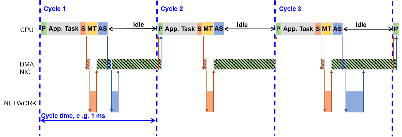
Cyclic frames with DC
Application has to perform:
/* Job P: Process data are saved in the process data image */
emExecJob(dwInstanceId, eUsrJob_ProcessAllRxFrames, &oJobParms);

/* App. Task */

/* Job S: Send updated process data.
   Outputs are updated in slaves and input data is collected to be present for the next cycle.
   The process data image is saved during eUsrJob_ProcessAllRxFrames */
emExecJob(dwInstanceId, eUsrJob_SendAllCycFrames, EC_NULL);

/* Job MT: Trigger master state machines.
   Required to perform any status changes or internal administration tasks */
emExecJob(dwInstanceId, eUsrJob_MasterTimer, EC_NULL);
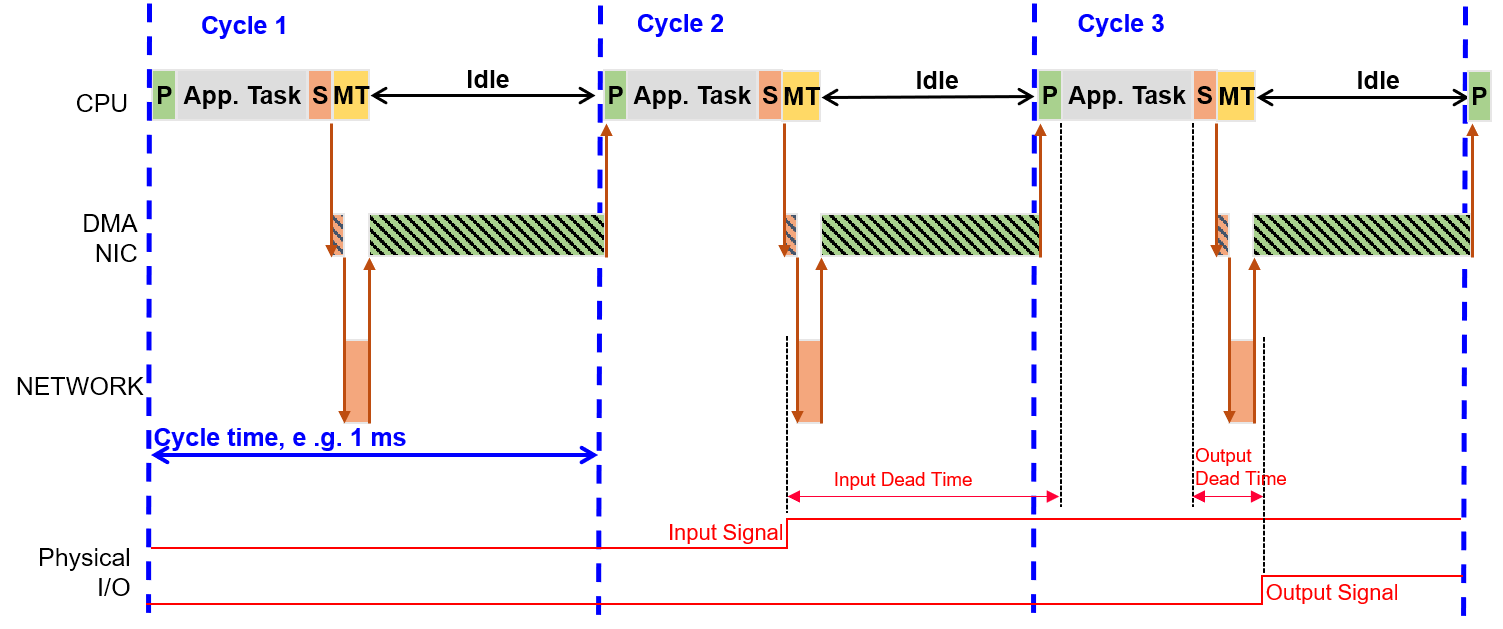
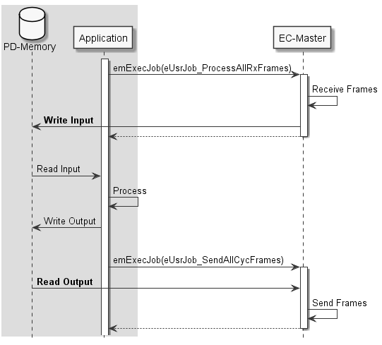
3.1.2. Alternative Timing: Short Input dead time
Application has to perform during startup:
emInitMaster(dwInstanceId, &oInitMasterParms);

/* create event for "cyclic frame received" and register RX callback function */
{
    EC_T_CYCFRAME_RX_CBDESC oCycFrameRxCallbackDesc;

    S_pvCycFrameReceivedEvent = OsCreateEvent();

    /* setup callback function which is called after RX */
    OsMemset(&oCycFrameRxCallbackDesc, 0, sizeof(EC_T_CYCFRAME_RX_CBDESC));
    oCycFrameRxCallbackDesc.pfnCallback = CycFrameReceivedCallback;
    oCycFrameRxCallbackDesc.pCallbackContext = S_pvCycFrameReceivedEvent;

    emIoCtl(dwInstanceId, EC_IOCTL_REGISTER_CYCFRAME_RX_CB, &oCycFrameRxCallbackDesc, sizeof(EC_T_CYCFRAME_RX_CBDESC), EC_NULL, 0, EC_NULL);
}
/* create cyclic process data Thread */
S_pvtJobThread = OsCreateThread((EC_T_CHAR*)"EcMasterJobTask", EcMasterJobTask, CpuSet,
    JOBS_THREAD_PRIO, JOBS_THREAD_STACKSIZE, (EC_T_VOID*)pAppContext);
Application has to perform inside job task:
/* Job S: Send updated process data.
   Outputs are updated in slaves and input data is collected to be present for the current cycle.
   The process data image is saved after receiving the response frame within the interrupt service thread */
emExecJob(dwInstanceId, eUsrJob_SendAllCycFrames, EC_NULL);

/* wait until cyclic frame is received */
OsWaitForEvent(S_pvCycFrameReceivedEvent, dwCycleTime);

/* App. Task */

/* Job MT: Trigger master state machines.
   Required to perform any status changes or internal administration tasks */
emExecJob(dwInstanceId, eUsrJob_MasterTimer, EC_NULL);

/* Job AS: Transmission of the acyclic commands from the queue.
   These may have been queued by the application or by the internal administration task (eUsrJob_MasterTimer) */
emExecJob(dwInstanceId, eUsrJob_SendAcycFrames, EC_NULL);
For closer details find an example project Examples/EcMasterDemoSyncSm
3.2. Example application
The example application EcMasterDemo handles the following tasks:
Showing basic EtherCAT communication
Master stack initialization
Start (set all slaves into OPERATIONAL state)
“Out of the box” solution for different operating systems, see Platform and Operating Systems (OS)
Thread with periodic tasks and application thread already implemented
- The output messages of the demo application will be printed on the console as well as in some files. The following log files will be created:
ecmaster0.logall messageserror0.logapplication error messages (logged via LogError function)
3.2.1. File reference
The EC-Master Demo application consists of the following files:
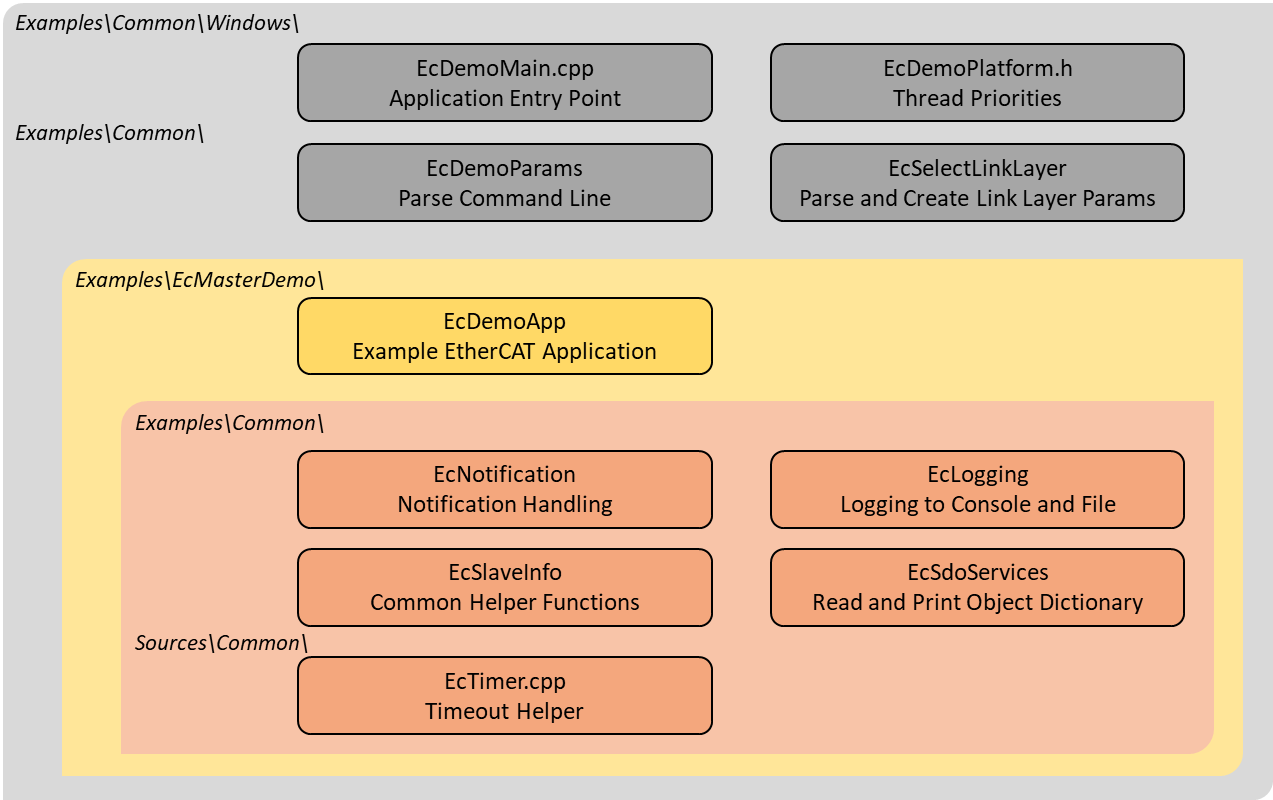
EcDemoMain.cppEntrypoint for the different operating systems
EcDemoPlatform.hOperating system specific settings (taskpriorities, timer settings)
EcDemoApp.cppInitialize, start and terminate the EtherCAT master
EcDemoApp.hApplication specific settings for EcDemoApp
EcDemoParms.cppParsing of command line parameters
EcDemoParms.hBasic configuration structs and parameters (EtherCAT master parameter)
EcSelectLinkLayer.cppCommon Functions which abstract the command line parsing into Link Layer parameters
EcNotification.cppSlave monitoring and error detection (function
emNotify())EcSdoServices.cppCoE object dictionary example
EcSlaveInfo.cppSlave information services (bus scan, slave properties, getting information of slaves connected to the EtherCAT bus)
EcLogging.cppMessage logging functions
EcTimer.cppStart and monitor timeouts
3.2.2. Master lifecycle
This chapter provides a brief overview of starting and stopping the EC-Master. Basically the operation of the EC-Master is wrapped between the functions:
and
The EC-Master is made ready for operation and started with the first two functions mentioned. During this preparation, a thread is set up and started that handles all the cyclic tasks of the EC-Master. The last function stops the EC-Master and clears the memory. The following sequence diagram gives an overview of the complete life cycle.
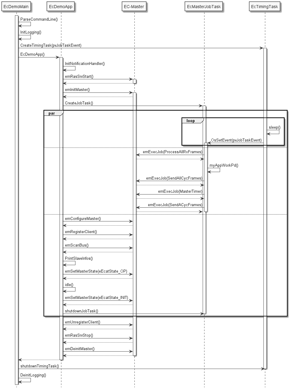
A more detailed description of the functions:
- EcDemoMain()
A wrapper to start the demo from the respective operating system. In addition to initializing the operating system, parsing command line parameters, and initializing logging, it also starts the timing task.
- EcDemoApp()
Demo application. The function takes care of starting and stopping the master and all related tasks. In between, the function runs idle, while all relevant work is done by the EcMasterJobTask().
- EcMasterJobTask()
Thread that does the necessary periodic work. Very important here is
myAppWorkpd()betweenEC_T_USER_JOB::eUsrJob_ProcessAllRxFramesandEC_T_USER_JOB::eUsrJob_SendAllCycFrames. Application-specific working on process data, which must be synchronous with the bus cycle, can be carried out here.- EcTimingTask()
Timing Thread. This thread sets the timing event that triggers the EcMasterJobTask for the next cycle.
- emInitMaster()
EC-Master API function: Prepare the master for operation and set operational parameters, e.g. used Link Layer, buffer sizes, maximum number of slaves, … .
- emConfigureMaster()
EC-Master API function: Loads the configuration from the ENI (XML file).
- emRegisterClient()
EC-Master API function: Register the application as a client at the EC-Master to receive event notifications.
- emSetMasterState()
EC-Master API function: Startup the EtherCAT master and switch the bus to the different states from INIT to OPERATIONAL.
- emDeinitMaster()
EC-Master API function: Clean up.
3.2.3. Synchronization
This chapter puts the tasks or functions, which run in the “tEcJobTask()”, into relation with timing and communication on the EtherCAT bus. See Picture.
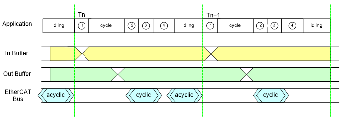
- Application
Shown are the tasks/jobs (1) through (4) which must be done by the application every single cycle. The details of the individual tasks are described below. When the application is done with the jobs, it waits for the next cycle. (period between (4) and (1)).
- In buffer
Shown are the contents of the input section of the process image. The contents are not valid while the EtherCAT master updates the data (1).
- Out buffer
Shown are the contents of the output section of the process image. The contents are not valid while the application updates the data (1).
- EtherCAT bus
Shown are the timing positions, when the EtherCAT master does cyclic and acyclic communication on the EtherCAT bus. Besides the timing position of the start for the cyclic frames, the shown positions may vary, depending on the number of frames.
In the “EcDemoApp()” application the tasks/jobs (1) through (4) shown in the picture are managed and scheduled by the “tEcJobTask()”. Here a more detailed description:
- Job 1
The job
EC_T_USER_JOB::eUsrJob_ProcessAllRxFramesworks on the frames and data received with previous bus activity. This includes cyclic as well as acyclic frames. The received frames are analyzed for new input data and the local process image is updated. During this process the input data section of the process image is invalid.- cycle
In the current myAppWorkpd(): Call ELxxxx() slave functions. The function
myAppWorkpd()allows application-specific working on process data. In this function, the application can use updated input information from JobP, perform calculations and manipulations, and write new data to the output section of the process image.- Job 2
This function triggers the transmission of all cyclic frames on the EtherCAT bus.
- Job 3
The job
EC_T_USER_JOB::eUsrJob_MasterTimerhas administrative character and are basically necessary to run the timeout timers. There is no interaction with the process image during these calls nor does this call trigger any bus traffic. It is not necessary to run this function with every bus cycle, especially on systems with short cycle times < 1 msec. But it is recommended to run this function with a 1 msec period.- Job 4
With the job
EC_T_USER_JOB::eUsrJob_SendAcycFramescall, the acyclic frames are scheduled for transmission.- idling
Currently implemented as waiting for the next cycle (triggered by the timing event).
3.2.4. Event notification
The EtherCAT master provides event notification for a great number of events. These events are for example:
Bus state change
Link state change
Working counter errors
…
Any thread can register for these events to be notified. This is achieved by calling the API function
-
EC_T_DWORD emRegisterClient(EC_T_DWORD dwInstanceID, EC_PF_NOTIFY pfnNotify, EC_T_VOID *pCallerData, EC_T_REGISTERRESULTS *pRegResults)
In case of the EcMasterDemo the class CEmNotification is provided. It implements the complete framework to catch and handle the EC-Master notifications. The class is instantiated once and registered at the EC-Master with the call emRegisterClient() shown above. The class implements the method ecatNotify() as major entry point (or callback function) for events.
There are two different ways events can be handled. The method of handling an event is primarily determined by the time required to handle the event and the processing context in which the event is to be handled. The methods are described below.
3.2.4.1. Direct notification handling
Smaller events can be handled directly in the context in which they are detected. A possible example of such an event is the detection of a false work counter (WKC). The procedure is as follows:
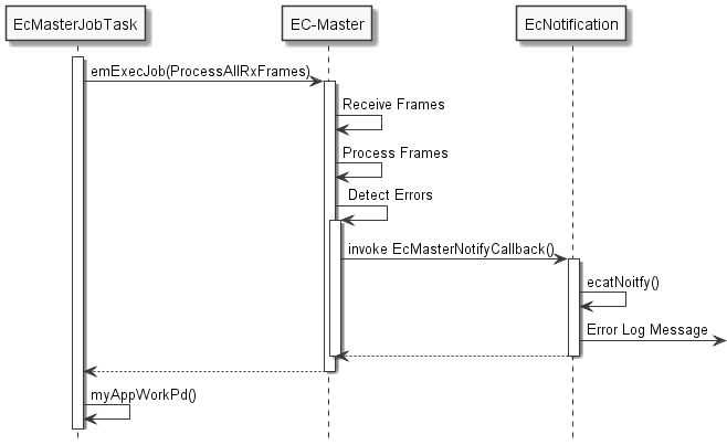
The event handling is reduced to simply issuing a log message, which is not time critical. The event is handled directly within the context of the emExecJob() ( eUsrJob_ProcessAllRxFrames) function.
3.2.4.2. Postponed notification handling
Events that require more time-consuming processing cannot be handled directly in the context in which they are detected. The handling or processing of the event must be postponed. This is accomplished through a queue, which is also readily implemented using the CEmNotification class. The procedure is as follows:
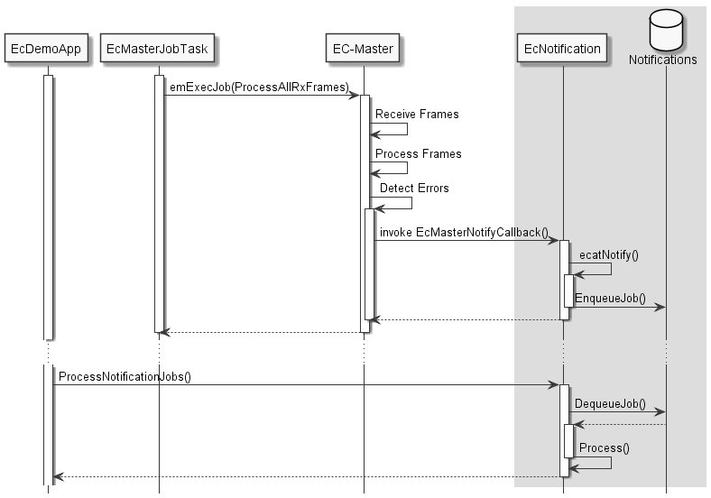
By calling periodically CEmNotification::ProcessNotificationJobs(), the application checks and handles all queued notifications.
Important
The call of CEmNotification::ProcessNotificationJobs() shall NOT be executed in the EcMasterJobTask(). As the CPU time consumption may be high, this would have a high impact to the real-time behavior of the cyclic operation.
3.2.5. Logging
The EcMasteDemo examples demonstrate how log messages can be processed by the application, see Examples/Common/EcLogging.cpp.
The messages processed by EcLogging.cpp are of different types, e.g. EC-Master log messages, application messages, DCM messages and are logged to the console and/or files.
Identical messages are skipped automatically by default.
Note
With some operating systems, logging in files is deactivated, e.g. because a file system is not available.
3.2.5.1. Parameters
The verbosity of the EcMasteDemo is specified as a -v command line parameter. It is used to determine the log level of the application, see EcDemoMain.cpp.
For performance reasons the EC-Master automatically filters log messages according to EC_T_LOG_PARMS::dwLogLevel.
EcLogging.cpp has various parameters beside the log level, like Roll Over setting, log task prio and affinity, log buffer size, etc. See EcMasteDemo for reference.
3.2.5.2. Configure EC-Master logging
The EC-Master logging is configured on initialization, see EC_T_INIT_MASTER_PARMS::LogParms in emInitMaster().
The application can provide customized log message handlers of type EC_PF_LOGMSGHK if the default handler in EcLogging.cpp does not fulfill the needs of the application.
Note
The callback is typically called from the context of the EcMasterJobTask and should return as fast as possible.
3.3. Master startup
The master stack has to be initialized once when the application is starting. After this one-time initialization one or more clients may register with the master. Finally, after all clients are registered the master can be started. Starting the master means that all slaves will be set into the operational state. Every time the state of the master has changed the clients are notified about this state-change.
3.3.1. Asynchronous (deferred) startup
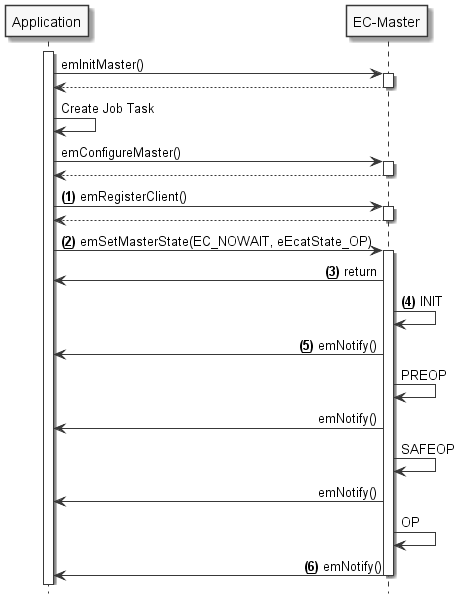
Application calls
emInitMaster()(…)Application creates Job Task. See Master lifecycle
Application calls
emConfigureMaster()(…)Application calls
emRegisterClient()(…) (See “1” )Application calls
emSetMasterState()(…) with a timeout parameterEC_NOWAIT(See “2” )Function
emSetMasterState()(…) returns immediately (EC_NOWAIT) (See “3” )Inside
emSetMasterState()(…) the master startup procedure will be initiated (See “4” )The master initializes all slaves until all slaves reach OPERATIONAL state
After every state change the application will be notified (See “5” )
After reaching the OPERATIONAL state the system is ready (See “6” )
3.3.2. Synchronous startup
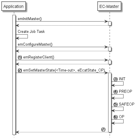
Application calls
emInitMaster()(…)Application creates Job Task. See Master lifecycle
Application calls
emConfigureMaster()(…)Application calls
emRegisterClient()(…) (See “1” )Application calls
emSetMasterState()(…) with an appropriate timeout value (See “2” )Inside
emSetMasterState()(…) the master startup procedure will be initiated (See “3” )The application is blocked until the whole startup has finished(See “7” )
The master initializes all slaves until all slaves reach OPERATIONAL state(See “3-6” )
After reaching the OPERATIONAL state the system is ready (See “6” )
emSetMasterState()(…)returns(See “7” )
3.4. EtherCAT Network Configuration ENI
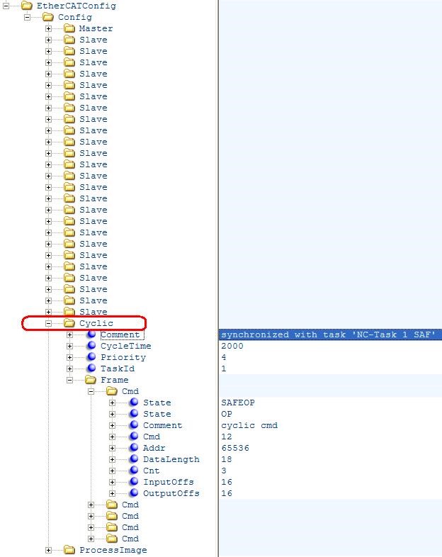
For reading new input data values and writing new output data values (process data update) the EtherCAT configuration file contains one or multiple “Cyclic” entries. These entries contain one or multiple frames (so-called cyclic frames) to be sent cyclically by the master. Inside the cyclic frames there are one or multiple EtherCAT datagrams containing logical read/write commands for reading and writing process data values.
3.4.1. Single cyclic entry configuration
By default there is only a single cyclic entry with one or more cyclic frames:
All process data synchronization modes support this configuration variant.
3.4.2. Multiple cyclic entries configuration
For more complex scenarios it is possible to configure the system using multiple cyclic entries with one or more cyclic frames for each cyclic entry.
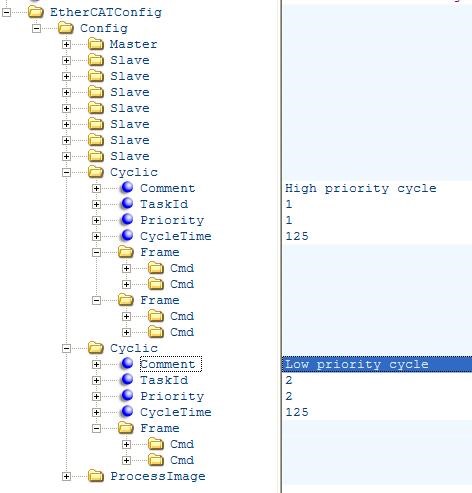
The application has to use the EC_T_USER_JOB::eUsrJob_SendCycFramesByTaskId job call to the master to send the appropriate cyclic frame.
See also
3.4.3. Copy Information for Slave-to-Slave communication
It is possible to configure the system to copy input variables to output variables within EC-Master. The copy info declarations of the corresponding received cyclic frame are processed in emExecJob(eUsrJob_ProcessAllRxFrames).
The exchange of process data takes two communication cycles. The duration is necessary if cable redundancy is used or if the WKC of INPUT needs to be checked before changing OUTPUT.
The copy info declarations are located at /EtherCATConfig/Config/Cyclic/Frame/Cmd/CopyInfos in the ENI file.
See also
CopyInfosType in ETG.2100
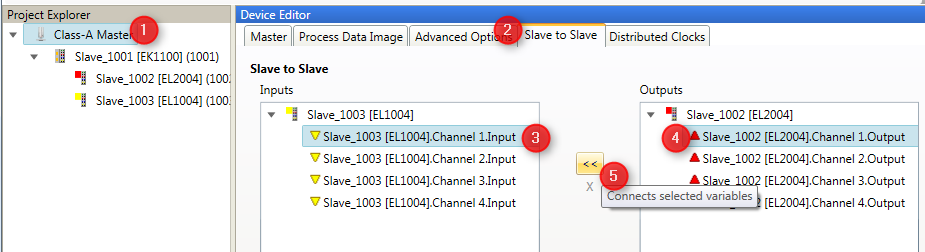
Configuration with EC-Engineer
- In the “Slave to Slave” tab of the Master select Input and Output Variable and connect them:
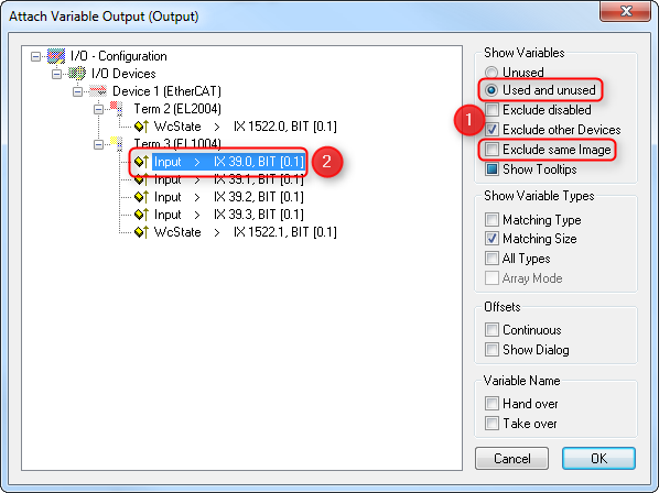
Configuration with ET9000
- Select “Linked to…” from the Output Variable:
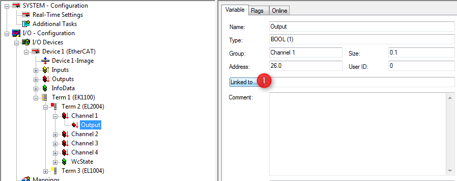
- Select Input Variable to be attached to the Output Variable:
Hint
Copy info declaration processing is independent of WKC values, but updating the INPUT source depends on successful Cyclic cmd WKC validation.
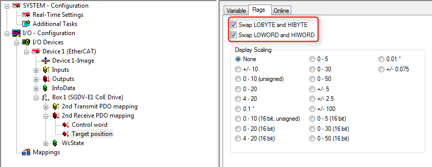
3.4.4. Swap bytes of variables according to ENI
The following screenshot (ET9000) shows how to configure variables to be swapped by the EC-Master:
Hint
The EC-Master does not distinguish between WORD or BYTE swapping. Setting any PDO swap flag instructs the EC-Master to swap the PDO variable.
The swap declarations are located at DataType’s attribute SwapData of RxPdo or TxPdo, e.g. /EtherCATConfig/Config/Slave/ProcessData/RxPdo/Entry/DataType in the ENI file.
3.5. Process Data Access
The process data is exchanged as variables between the EtherCAT master and the slaves with EtherCAT commands every cycle.
The Master Memory contains the Process Data Image separated in two memory areas, one for input data and another one for output data:

The base addresses of these areas are provided by calling the functions emGetProcessImageInputPtr() and emGetProcessImageOutputPtr().
The size of the Process Data Image INPUT/OUTPUT areas as defined in the ENI file under EtherCATConfig/Config/ProcessImage/Inputs/ByteSize and EtherCATConfig/Config/ProcessImage/Outputs/ByteSize is returned by emRegisterClient() at EC_T_REGISTERRESULTS::dwPDOutSize and EC_T_REGISTERRESULTS::dwPDInSize.
All INPUT and OUTPUT process data variables are mapped and contained in the Process Data Image:
The information about variables is loaded from the ENI file using emConfigureMaster():
/* load ENI */
const EC_T_CHAR* szFileName = "eni.xml";
dwRes = emConfigureMaster(dwInstanceId, eCnfType_Filename,
    (EC_T_BYTE*)szFileName, (EC_T_DWORD)OsStrlen(szFileName));
To get the list of all variables, the example application EcMasterDemo can be started with command line option -printvars, see Running EcMasterDemo.
It demonstrates the usage of the functions emGetSlaveInpVarInfoEx() and emGetSlaveOutpVarInfoEx().
Sizes of EtherCAT variables are given as bit length, not byte length and their offset within the Process Data Image are given as bit offsets, not byte offsets.
Due to padding bits within the Process Data Objects (PDOs) defined in the EtherCAT slave description (ESI file) and the calculation algorithms within the configuration tool, process data variables are typically starting at a byte boundary.
The structure of the process data image is read from the ENI file. It includs all offsets of all process data variables and does not change until a new configuration is provided.
Lookup of variables is therefor only needed once after loading the network configuration (ENI) and is not needed every cycle.
In the example program it can be integrated in myAppPrepare() at application startup.
All variables names are stored in the ENI file under EtherCATConfig/Config/ProcessImage/[Inputs|Outputs]/Variable.
Application-specific working on process data is supposed to be integrated in myAppWorkPd() .
Different ways to lookup informations of variables using the parsed information from the ENI by the EC-Master stack in myAppPrepare()
and Application-specific working on process data in myAppWorkPd() is described in this chapter below.
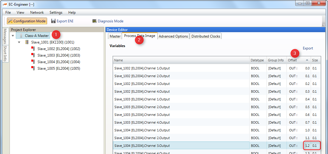
3.5.1. Process data access using hard coded offsets
The configuration tool assigns the offset and size of each variable within the Process Data Image:

The following example demonstrates how to access the variables with hard coded bit offsets in myAppWorkPd().
Process data access using hard coded offsets example
static EC_T_DWORD myAppWorkpd(T_EC_DEMO_APP_CONTEXT* pAppContext)
{
    EC_T_DWORD dwInstanceId = pAppContext->dwInstanceId;
    EC_T_BYTE* pbyPdIn = emGetProcessImageInputPtr(dwInstanceId);
    EC_T_BYTE* pbyPdOut = emGetProcessImageOutputPtr(dwInstanceId);

    /* Slave_1002 [EC-Training Generator].Counter1.Value (Offset: 9.0) */
    EC_T_SDWORD sdwCounter1_Value = EC_GET_FRM_DWORD(&pbyPdIn[9 /* 9.0 */]);
    EcLogMsg(EC_LOG_LEVEL_INFO, (pEcLogContext, EC_LOG_LEVEL_INFO,
        "Counter1.Value: %d\n", sdwCounter1_Value));

    /* Slave_1002 [EC-Training Generator].Counter1.Enable (Offset: 11.0) */
    EC_T_BYTE byCounter1_Enable = 1;
    EC_COPYBIT(&pbyPdOut[11], 0 /* 11.0 */, byCounter1_Enable);

    /* Slave_1002 [EC-Training Generator].Counter1.Increment (Offset: 9.0) */
    EC_T_SWORD swCounter1_Increment = 100;
    EC_SET_FRM_WORD(&pbyPdIn[9 /* 9.0 */], swCounter1_Increment);

    return EC_E_NOERROR;
}
Note
The offsets are subject to be changed if the ENI file changes. It is strongly recommended to determine the bit offsets of variables on startup as described in the following chapters instead of using hard coded values!
3.5.2. Process data access using variable names from ENI
Using the configuration tool, unique names can be assign to Process Data variables. They are included in the ENI file.
Note
The variable name parameter to emFindOutpVarByNameEx() / emFindInpVarByNameEx() must match the variable name in the ENI file. The variable names of each slave are taken from the ESI file and can be changed using the configuration tool.
The following example demonstrates how to query the bit offset of a variable by its name from the EC-Master stack using emFindOutpVarByNameEx(), emFindInpVarByNameEx().
Process data access using variable names from ENI example
struct _T_MY_APP_DESC;
typedef struct _T_EC_DEMO_APP_CONTEXT
{
    T_EC_DEMO_APP_PARMS    AppParms;
    EC_T_LOG_PARMS         LogParms;
    EC_T_DWORD             dwInstanceId;
    struct _T_MY_APP_DESC* pMyAppDesc;
} T_EC_DEMO_APP_CONTEXT;

typedef struct _T_MY_APP_DESC
{
    EC_T_PROCESS_VAR_INFO_EX aoProcVarInfo[3];
} T_MY_APP_DESC;

static EC_T_DWORD myAppPrepare(T_EC_DEMO_APP_CONTEXT* pAppContext)
{
    EC_T_DWORD dwRetVal = EC_E_NOERROR;
    EC_T_DWORD dwInstanceId = pAppContext->dwInstanceId;
    T_MY_APP_DESC* pMyAppDesc = pAppContext->pMyAppDesc;
    EC_T_PROCESS_VAR_INFO_EX* aoProcVarInfo = pMyAppDesc->aoProcVarInfo;

    OsMemset(pMyAppDesc->aoProcVarInfo, 0, sizeof(pMyAppDesc->aoProcVarInfo));

    dwRetVal = emFindInpVarByNameEx(dwInstanceId, "Slave_1002 [EC-Training Generator].Counter1.Value", &aoProcVarInfo[0]);
    if (EC_E_NOERROR != dwRetVal)
        return dwRetVal;

    dwRetVal = emFindOutpVarByNameEx(dwInstanceId, "Slave_1002 [EC-Training Generator].Counter1.Enable", &aoProcVarInfo[1]);
    if (EC_E_NOERROR != dwRetVal)
        return dwRetVal;

    dwRetVal = emFindOutpVarByNameEx(dwInstanceId, "Slave_1002 [EC-Training Generator].Counter1.Increment", &aoProcVarInfo[2]);
    if (EC_E_NOERROR != dwRetVal)
        return dwRetVal;

    return EC_E_NOERROR;
}
static EC_T_DWORD myAppWorkpd(T_EC_DEMO_APP_CONTEXT* pAppContext)
{
    EC_T_DWORD dwInstanceId = pAppContext->dwInstanceId;
    T_MY_APP_DESC* pMyAppDesc = pAppContext->pMyAppDesc;
    EC_T_PROCESS_VAR_INFO_EX* aoProcVarInfo = pMyAppDesc->aoProcVarInfo;

    EC_T_BYTE* pbyPdIn = emGetProcessImageInputPtr(dwInstanceId);
    EC_T_BYTE* pbyPdOut = emGetProcessImageOutputPtr(dwInstanceId);

    /* Slave_1002 [EC-Training Generator].Counter1.Value (Offset: 9.0) */
    EcLogMsg(EC_LOG_LEVEL_INFO, (pEcLogContext, EC_LOG_LEVEL_INFO,
        "Counter1.Value: %d\n", EC_GET_FRM_DWORD(&pbyPdIn[aoProcVarInfo[0].nBitOffs / 8])));

    /* Slave_1002 [EC-Training Generator].Counter1.Enable (Offset: 11.0) */
    EC_SETBIT(pbyPdOut, aoProcVarInfo[1].nBitOffs);

    /* Slave_1002 [EC-Training Generator].Counter1.Increment (Offset: 9.0) */
    EC_SET_FRM_WORD(&pbyPdOut[aoProcVarInfo[2].nBitOffs / 8], 100);

    return EC_E_NOERROR;
}
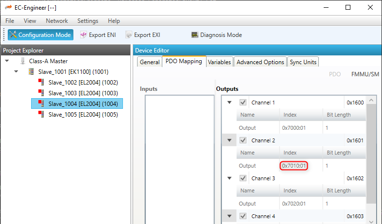
3.5.3. Process data access using variable object index from ENI
The variable offsets can be determined dynamically using the object index and subindex with the functions emGetSlaveInpVarByObjectEx() or emGetSlaveOutpVarByObjectEx().
The “PDO Mapping” tab in EC-Engineer shows the Object Index and SubIndex for each variable:
The following example demonstrates how to query the bit offset of a variable by its Process Data variable Object Index and SubIndex from the EC-Master stack using emGetSlaveOutpVarByObjectEx(), emGetSlaveInpVarByObjectEx().
Process data access using variable object index from ENI example
struct _T_MY_APP_DESC;
typedef struct _T_EC_DEMO_APP_CONTEXT
{
    T_EC_DEMO_APP_PARMS    AppParms;
    EC_T_LOG_PARMS         LogParms;
    EC_T_DWORD             dwInstanceId;
    struct _T_MY_APP_DESC* pMyAppDesc;
} T_EC_DEMO_APP_CONTEXT;

typedef struct _T_MY_APP_DESC
{
    EC_T_PROCESS_VAR_INFO_EX aoProcVarInfo[3];
} T_MY_APP_DESC;

static EC_T_DWORD myAppPrepare(T_EC_DEMO_APP_CONTEXT* pAppContext)
{
    EC_T_DWORD dwRetVal = EC_E_NOERROR;
    EC_T_DWORD dwInstanceId = pAppContext->dwInstanceId;
    T_MY_APP_DESC* pMyAppDesc = pAppContext->pMyAppDesc;
    EC_T_PROCESS_VAR_INFO_EX* aoProcVarInfo = pMyAppDesc->aoProcVarInfo;

    OsMemset(pMyAppDesc->aoProcVarInfo, 0, sizeof(pMyAppDesc->aoProcVarInfo));

    /* Slave_1002 [EC-Training Generator].Counter1.Value (Object 0x6000:01) */
    dwRetVal = emGetSlaveInpVarByObjectEx(dwInstanceId, EC_TRUE, 1002, 0x6000, 1, &aoProcVarInfo[0]);
    if (EC_E_NOERROR != dwRetVal)
        return dwRetVal;

    /* Slave_1002 [EC-Training Generator].Counter1.Enable (Object 0x7000:01) */
    dwRetVal = emGetSlaveOutpVarByObjectEx(dwInstanceId, EC_TRUE, 1002, 0x7000, 1, &aoProcVarInfo[1]);
    if (EC_E_NOERROR != dwRetVal)
        return dwRetVal;

    /* Slave_1002 [EC-Training Generator].Counter1.Increment (Object 0x7000:02) */
    dwRetVal = emGetSlaveOutpVarByObjectEx(dwInstanceId, EC_TRUE, 1002, 0x7000, 2, &aoProcVarInfo[2]);
    if (EC_E_NOERROR != dwRetVal)
        return dwRetVal;

    return EC_E_NOERROR;
}
static EC_T_DWORD myAppWorkpd(T_EC_DEMO_APP_CONTEXT* pAppContext)
{
    EC_T_DWORD dwInstanceId = pAppContext->dwInstanceId;
    T_MY_APP_DESC* pMyAppDesc = pAppContext->pMyAppDesc;
    EC_T_PROCESS_VAR_INFO_EX* aoProcVarInfo = pMyAppDesc->aoProcVarInfo;

    EC_T_BYTE* pbyPdIn = emGetProcessImageInputPtr(dwInstanceId);
    EC_T_BYTE* pbyPdOut = emGetProcessImageOutputPtr(dwInstanceId);

    /* Slave_1002 [EC-Training Generator].Counter1.Value (Object 0x6000:01) */
    EcLogMsg(EC_LOG_LEVEL_INFO, (pEcLogContext, EC_LOG_LEVEL_INFO,
        "Counter1.Value: %d\n", EC_GET_FRM_DWORD(&pbyPdIn[aoProcVarInfo[0].nBitOffs / 8])));

    /* Slave_1002 [EC-Training Generator].Counter1.Enable (Object 0x7000:01) */
    EC_SETBIT(pbyPdOut, aoProcVarInfo[1].nBitOffs);

    /* Slave_1002 [EC-Training Generator].Counter1.Increment (Object 0x7000:02) */
    EC_SET_FRM_WORD(&pbyPdOut[aoProcVarInfo[2].nBitOffs / 8], 100);

    return EC_E_NOERROR;
}
3.5.4. Process data access using slave station address
Based on the unique station address of a specific slave the base offset of INPUTs and OUTPUTs can be determined using emGetCfgSlaveInfo().
The offsets are stored in EC_T_CFG_SLAVE_INFO::dwPdOffsIn and EC_T_CFG_SLAVE_INFO::dwPdOffsOut:
The following example demonstrates how to query the bit offset of a slave’s process data by its station address from the EC-Master stack using emGetCfgSlaveInfo() .
Process data access using slave station address example
static EC_T_DWORD myAppPrepare(T_EC_DEMO_APP_CONTEXT* pAppContext)
{
    EC_T_DWORD dwRetVal       = EC_E_NOERROR;
    EC_T_DWORD dwInstanceId   = pAppContext->dwInstanceId;
    T_MY_APP_DESC* pMyAppDesc = pAppContext->pMyAppDesc;
    OsMemset(pMyAppDesc->aSlaveList, 0, sizeof(pMyAppDesc->aSlaveList));

    dwRetVal = emGetCfgSlaveInfo(dwInstanceId, EC_TRUE, 1001, &pMyAppDesc->aSlaveList[0]);
    if (EC_E_NOERROR != dwRetVal)
        return dwRetVal;

    dwRetVal = emGetCfgSlaveInfo(dwInstanceId, EC_TRUE, 1002, &pMyAppDesc->aSlaveList[1]);
    if (EC_E_NOERROR != dwRetVal)
        return dwRetVal;

    return EC_E_NOERROR;
}
static EC_T_DWORD myAppWorkpd(T_EC_DEMO_APP_CONTEXT* pAppContext)
{
    EC_T_DWORD dwInstanceId = pAppContext->dwInstanceId;
    T_MY_APP_DESC* pMyAppDesc = pAppContext->pMyAppDesc;

    EC_T_BYTE* pbyPdIn = emGetProcessImageInputPtr(dwInstanceId);
    EC_T_BYTE* pbyPdOut = emGetProcessImageOutputPtr(dwInstanceId);

    /* Slave_1002 [EC-Training Generator].Counter1.Value (first INPUT variable) */
    EC_T_SDWORD* psdwCounter1Value = (EC_T_SDWORD*)&(pbyPdIn[pMyAppDesc->aSlaveList[1].dwPdOffsIn / 8]);

    EcLogMsg(EC_LOG_LEVEL_INFO, (pEcLogContext, EC_LOG_LEVEL_INFO,
        "Counter1.Value: %d\n", EC_GET_FRM_DWORD(psdwCounter1Value)));

    /* Slave_1002 [EC-Training Generator].Counter1.Increment (first OUTPUT variable) */
    EC_T_SWORD* pswCounter1Increment = (EC_T_SWORD*)&(pbyPdOut[pMyAppDesc->aSlaveList[1].dwPdOffsOut / 8]);
    EC_SET_FRM_WORD(pswCounter1Increment, 100);

    return EC_E_NOERROR;
}
See also
Note
A slave may have multiple sync units with individual offsets and sizes, see EC_T_CFG_SLAVE_INFO::dwPdOffsIn2 EC_T_CFG_SLAVE_INFO::dwPdOffsOut2, … .
Note
The example application EcMasterDemo demonstrates the usage of emGetCfgSlaveInfo() with its process data OUPPUT flashing. See command line option -flash in Running EcMasterDemo.
3.5.5. Process data access using generated PD layout C-header file
The EC-Engineer can export the process variables to a PD layout C-header file via the menu item as shown in the following screenshots:
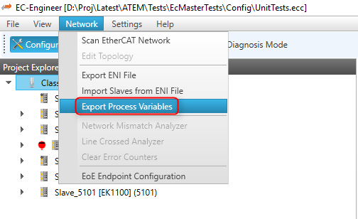
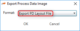
This will generate a header file containing the variables of the slaves as follows:
#define PDLAYOUT_IN_OFFSET_SLAVE_1002 9
typedef struct _T_PDLAYOUT_IN_SLAVE_1002
{
    EC_T_SDWORD sdwCounter1_Value;       // Slave_1002 ...Counter1.Value
    EC_T_SWORD  swCounter1_NetworkClock; // Slave_1002 ...Counter1.NetworkClock
    EC_T_SDWORD sdwCounter2_Value;       // Slave_1002 ...Counter2.Value
    EC_T_SWORD  swCounter2_NetworkClock; // Slave_1002 ...Counter2.NetworkClock
} EC_PACKED(1) T_PDLAYOUT_IN_SLAVE_1002;
#include EC_PACKED_INCLUDESTOP

#include EC_PACKED_INCLUDESTART(1)
#define PDLAYOUT_OUT_OFFSET_SLAVE_1002 9
typedef struct _T_PDLAYOUT_OUT_SLAVE_1002
{
    EC_T_SWORD  swCounter1_Increment;    // Slave_1002 ...Counter1.Increment
    EC_T_BYTE   byCounter1_Enable : 1;   // Slave_1002 ...Counter1.Enable
    //...
} EC_PACKED(1) T_PDLAYOUT_OUT_SLAVE_1002;
#include EC_PACKED_INCLUDESTOP
The following example demonstrates how to access process data variables using a generated PD layout C-header file in myAppWorkPd().
Process data access using generated PD layout C-header file example
#include "pdlayout.h"
static EC_T_DWORD myAppWorkpd(T_EC_DEMO_APP_CONTEXT* pAppContext)
{
    EC_T_DWORD dwInstanceId = pAppContext->dwInstanceId;
    T_PDLAYOUT_IN* poPdIn = (T_PDLAYOUT_IN*)emGetProcessImageInputPtr(dwInstanceId);
    T_PDLAYOUT_OUT* poPdOut = (T_PDLAYOUT_OUT*)emGetProcessImageOutputPtr(dwInstanceId);

    /* Slave_1002 [EC-Training Generator].Counter1.Value (Offset: 9.0) */
    EcLogMsg(EC_LOG_LEVEL_INFO, (pEcLogContext, EC_LOG_LEVEL_INFO,
        "Counter1.Value: %d\n", EC_GET_FRM_DWORD(&poPdIn->sdwSlave_1002_Counter1_Value)));

    /* Slave_1002 [EC-Training Generator].Counter1.Enable (Offset: 11.0) */
    poPdOut->bySlave_1002_Counter1_Enable = 1;

    /* Slave_1002 [EC-Training Generator].Counter1.Increment (Offset: 9.0) */
    EC_SET_FRM_WORD(&poPdOut->swSlave_1002_Counter1_Increment, 100);

    return EC_E_NOERROR;
}
Note
The offsets from the PD layout C-header file (PdLayout.h) are byte offsets, not bit offsets!
It is possible to change the variable names of slaves before generating the PD layout C-header file to give them custom names:

This will generate a header file containing the customized variable names of the slaves as follows:
#include EC_PACKED_INCLUDESTART(1)
#define PDLAYOUT_OUT_OFFSET_EC_TRAINING_SAMPLER 0
typedef struct _T_PDLAYOUT_OUT_EC_TRAINING_SAMPLER
{
    EC_T_BYTE   byOutputDigital_Bit0 : 1;   // ...
    EC_T_BYTE   byOutputDigital_Bit1 : 1;   // ...
    EC_T_BYTE   byOutputDigital_Bit2 : 1;   // ...
    EC_T_BYTE   byOutputDigital_Bit3 : 1;   // ...
    EC_T_BYTE   byOutputDigital_Bit4 : 1;   // ...
    EC_T_BYTE   byOutputDigital_Bit5 : 1;   // ...
    EC_T_BYTE   byOutputDigital_Bit6 : 1;   // ...
    EC_T_BYTE   byOutputDigital_Bit7 : 1;   // ...
    EC_T_SWORD  swOutputAnalog_SpeedFactor; // ...
    EC_T_SWORD  swOutputAnalog_Reserved_2;  // ...
    EC_T_SWORD  swOutputAnalog_Reserved_3;  // ...
    EC_T_SWORD  swOutputAnalog_Reserved_4;  // ...
} EC_PACKED(1) T_PDLAYOUT_OUT_EC_TRAINING_SAMPLER;
#include EC_PACKED_INCLUDESTOP
Process data access example using generated PD layout C-header file with customized variable names of the slaves
#include "pdlayoutcustom.h"
static EC_T_DWORD myAppWorkpd(T_EC_DEMO_APP_CONTEXT* pAppContext)
{
    EC_T_DWORD dwInstanceId = pAppContext->dwInstanceId;
    T_PDLAYOUT_IN* poPdIn = (T_PDLAYOUT_IN*)emGetProcessImageInputPtr(dwInstanceId);
    T_PDLAYOUT_OUT* poPdOut = (T_PDLAYOUT_OUT*)emGetProcessImageOutputPtr(dwInstanceId);

    /* EC-Training-Generator.Counter1.Value (Offset: 9.0, Size: 4.0, Datatype: DINT) */
    EcLogMsg(EC_LOG_LEVEL_INFO, (pEcLogContext, EC_LOG_LEVEL_INFO,
        "Counter1.Value: %d\n", EC_GET_FRM_DWORD(&poPdIn->sdwEC_Training_Generator_Counter1_Value_Counter1_Value)));

    /* EC-Training-Generator.Counter1.Enable (Offset: 11.0, Size: 0.1, Datatype: BOOL) */
    poPdOut->byEC_Training_Generator_Counter1_Enable_Counter1_Enable = 1;

    /* EC-Training-Generator.Counter1.Increment (Offset: 9.0, Size: 2.0, Datatype: INT) */
    EC_SET_FRM_WORD(&poPdOut->swEC_Training_Generator_Counter1_Increment_Counter1_Increment, 100);

    return EC_E_NOERROR;
}
Note
The offsets are subject to be changed if the ENI file changes. It is strongly recommended to determine the bit offsets of the variables on startup e.g. by querying the bit offset of a slave’s process data by its station address from the EC-Master stack using emGetCfgSlaveInfo() as described in the previous chapters instead of using hard coded values!
3.5.6. Process Data Access Functions
Process data variables that are packed as array of bits are bit aligned and not byte aligned in process data. See EC_COPYBITS for how to copy data areas with bit offsets that are not byte aligned. Getting and setting bits that are bit aligned and not byte aligned should be done using EC_SETBITS and EC_GETBITS. Accessing complete EC_T_BYTE, EC_T_WORD, EC_T_DWORD, EC_T_QWORD can be accessed more efficiently using the appropriate macros according to the following table.
Note
These functions do not initiate any transmission on the line. Process data is typically transmitted as little endian and must therefore be swapped on big endian systems such as PPC in order to be correctly interpreted, see e.g. EC_SET_FRM_WORD, EC_GET_FRM_WORD .
Variable Type |
Bit Size |
EC Type |
Macro |
|---|---|---|---|
INTEGER8, UNSINGED8, BIT8 |
8 |
EC_T_BYTE |
N/A |
INTEGER16, UNSINGED16 |
16 |
EC_T_WORD |
|
INTEGER32, UNSINGED32, REAL32 |
32 |
EC_T_DWORD |
|
INTEGER64, UNSINGED64, REAL64 |
64 |
EC_T_UINT64 |
|
BOOLEAN, BIT1…BIT7 |
1 |
EC_T_BOOL |
3.6. Process Data Memory
All mapped process data objects of the slaves are copied by the master into a process data memory image. New input values received from the slaves are written to the input process data image. New output values to be sent to the slaves are read from the output process data image.
The EC-Master uses two separate buffers where process data input values and process data output values are stored. The buffers used may either be always the same (fixed buffers) or be changed on every process data transfer cycle (dynamic buffers).
The EC-Master has different options for how the process data memory is provided.
EC-Master provides process data memory (fixed buffers)
User application registers an external memory provider with fixed buffers
User application registers an external memory provider with dynamic buffers
3.6.1. EC-Master as process data memory provider
If the application does not register a memory provider, the EC-Master internally allocates the required memory needed to store input and output process data values during emConfigureMaster().
The EC-Master always uses the same buffers for reading/writing process data.
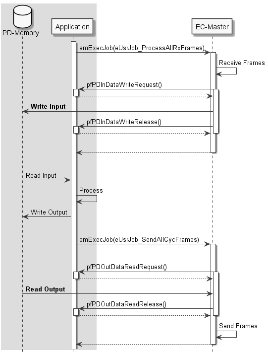
3.6.2. Application as process data memory provider with fixed buffers
The application may register a memory provider with emIoControl - EC_IOCTL_REGISTER_PDMEMORYPROVIDER in case the master shall use externally allocated memory to store input and output process data values.
The memory provider may optionally supply callback functions to synchronize memory access between the application and the EC-Master.
- Receiving new input process data:
- Sending new output process data:
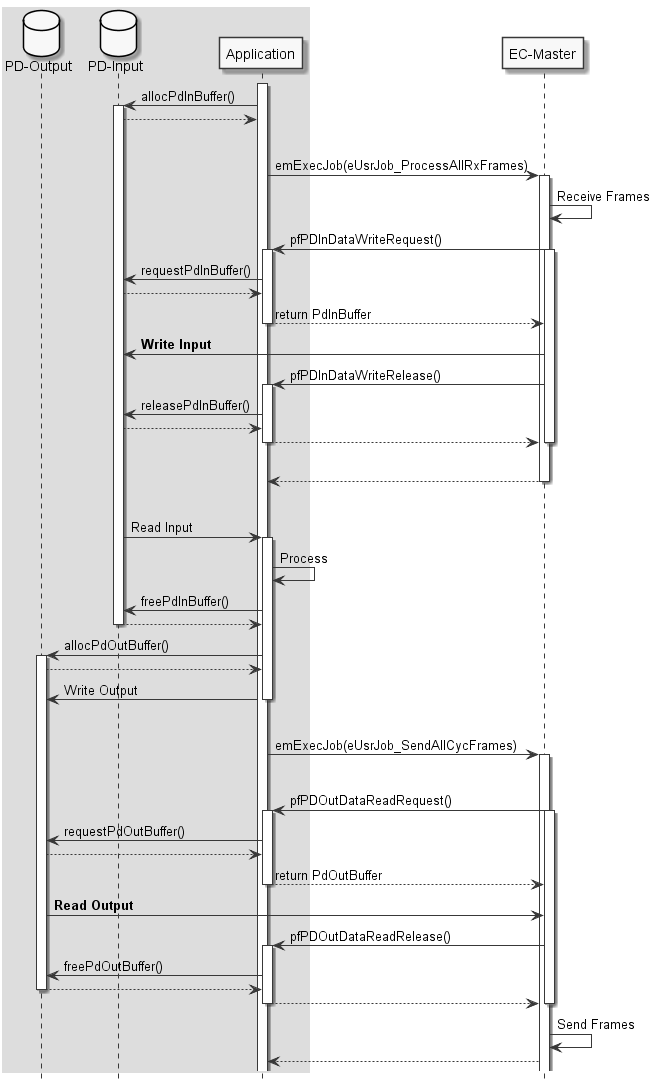
3.6.3. Application as process data memory provider with dynamic buffers
The application registers an external memory provider without fixed buffers via emIoControl - EC_IOCTL_REGISTER_PDMEMORYPROVIDER with the parameters EC_T_MEMPROV_DESC::pbyPDInData and EC_T_MEMPROV_DESC::pbyPDOutData set to EC_NULL. In this case, the EC-Master requests via the callback functions the buffer addresses cyclically when reading or writing process data. This mode can be used to implement dynamic buffering mechanisms between the application and the EC-Master, e.g. double buffering, triple buffering.
3.7. Error detection and diagnosis
The EC-Master API generally return EC_E_NOERROR or an error code.
One of the parameters that the client must set when registering with the EC-Master is a generic notification callback function (emNotify()). If an error is detected, the master calls this function.
The EC-Master log messages are enabled if EC_T_LOG_PARMS is configured as described in emInitMaster().
3.7.1. Cyclic cmd WKC validation
New input values received from the slaves will be written into the input process data memory only if the WKC of the corresponding datagram is not 0 and not greater than the configured WKC value.
3.7.2. WKC State in Diagnosis Image
Each cyclic Process Data cmd has its own WKC State bit in the diagnosis image. The state is updated on frame receiving, frame loss detection or link disconnection. All process data variables within a datagram have the same WKC State value. The WKC State bit is set to 1 if the WKC value is not as expected or 0. In case of MSU if all the commands related to the MSU return WKC 0, the WKC State will be set to 1.
The WKC State offset within the Diagnosis Image is available at EC_T_CFG_SLAVE_INFO and EC_T_PROCESS_VAR_INFO_EX, EC_T_MSU_INFO see emGetDiagnosisImagePtr(), emGetCfgSlaveInfo(), emGetSlaveInpVarInfoEx(), emGetSlaveOutpVarInfoEx(), emGetMasterSyncUnitInfo().
The application can check the WKC State of a variable e.g. as follows:
EC_T_CFG_SLAVE_INFO oSlaveInfo;
EC_T_BYTE* pbyDiagnosisImage = emGetDiagnosisImagePtr();
EC_T_BYTE byWkcState = 1;

if (EC_NULL != pbyDiagnosisImage)
{
    if (EC_NOERROR == emGetCfgSlaveInfo(EC_TRUE, 2302, &oSlaveInfo))
    {
        EC_GETBITS(pbyDiagnosisImage, &byWkcState, oSlaveInfo.wWkcStateDiagOffsOut[0], 1);
    }
}

if (1 == byWkcState)
{
    /* ... error ... */
}
See also
3.7.2.1. Behavior in case of automatically adjusted expected WKC value
Optionally, the expected WKC value can be automatically adjusted according the state and the presence of the slaves. See emIoControl - EC_IOCTL_SET_AUTO_ADJUST_CYCCMD_WKC_ENABLED. The WKC State bits change synchronized to the corresponding notification, e.g. on link disconnection all slaves disappear and the behavior is as follows:
All WKC State bits are set to 1 as missing data is not expected.
The Master notifies the application about the link disconnection and the disappearing of slaves
All WKC State bits are set to 0 as it is now expected to have no process data if all slaves are absent.
3.7.3. Master Sync Units
Figure out the MSU offsets by calling the function emGetMasterSyncUnitInfo(), as described in emGetMasterSyncUnitInfo().
3.8. Trace Data
Trace Data allows applications to trace data in real time on the network. To ensure real-time transmission, it is implemented as part of the cyclic process data.
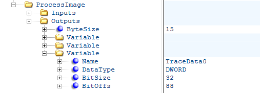
They are placed behind the slave output data in the output area of the process data image of the EtherCAT application.
The trace data area can be configured either via the ENI with the help of the EC-Engineer or without changing the ENI using the API emTraceDataConfig().
Trace Data can be captured with a network monitoring tool like Wireshark.
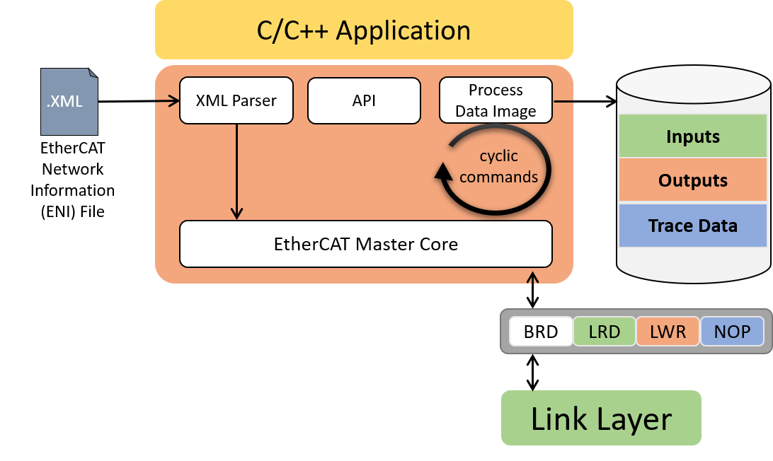
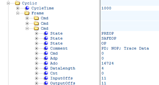
To transfer the data, an additional NOP cmd is appended to the end of the cyclic EtherCAT frame. The NOP cmd has ADP 0 and ADO 0x4154. The EC-Master automatically fills the data area of the NOP Cmd with the current trace data when sending cyclic frames. Since the trace data are transferred to the network as NOP Cmd, they are not evaluated by any ESC. Therefore, the WKC of the trace data remains 0 and the application cannot validate the data.
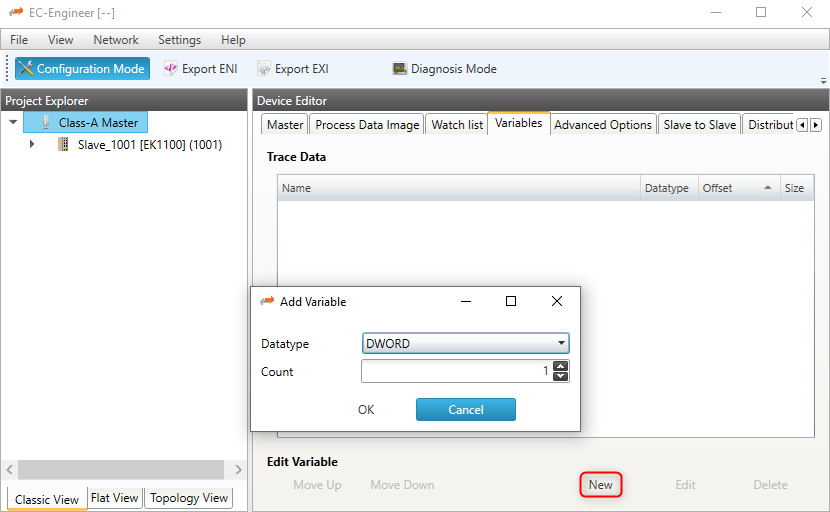
3.8.1. Trace Data configuration via EC-Engineer
The easiest and most comfortable way to create trace data variables is with the help of the EC-Engineer.
The necessary NOP cmd and the process data variables are automatically created and exported to the ENI. The process variables can be accessed as usual using the emFindOutpVarByNameEx() function.
- Trace data variables of any size and number can be created in the Variables tab of the EC-Engineer:
- The automatically created variable names can also be edited:
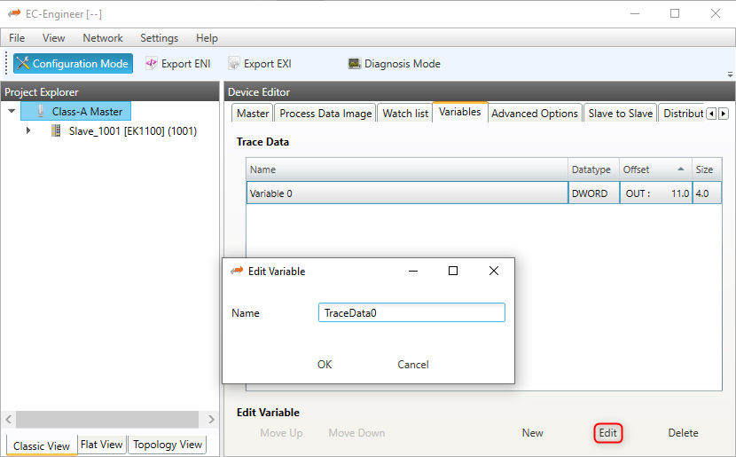
- The generated process variables can be found in the exported ENI file:
- As well as the NOP cmd:
3.8.2. Trace Data configuration via API
The application can configure the trace data size using the emTraceDataConfig() API.
The trace data configuration must take place between the initialization of the EC-Master (emInitMaster()) and the configuration of the network (emConfigureMaster()).
During emConfigureMaster() the EC-Master tries to expand the process image output area by the trace data buffer and generates the corresponding NOP cmd.
Access to the trace data buffer is via an offset to the process data output image. The offset can be determined via the API emTraceDataGetInfo().
Configuration of the trace data buffer:
//emInitMaster();

emTraceDataConfig(dwInstanceId, sizeof(EC_T_DWORD));

//emConfigureMaster();
Access to the trace data buffer:
EC_T_TRACE_DATA_INFO oTraceDataInfo;
emTraceDataGetInfo(dwInstanceId, &oTraceDataInfo);

EC_SET_FRM_DWORD(oTraceDataInfo.pbyData + oTraceDataInfo.dwOffset, 0x11223344);
Warning
Trace data, encapsulated in an additional EtherCAT Cmd, must fit in the first cyclic frame.
Trace data is not available for the fixed cyclic frame layout
EC_T_CYCFRAME_LAYOUT::eCycFrameLayout_FIXED.
3.9. EtherCAT Master Stack Source Code
In a source code delivery the master stack sources are divided into 4 parts:
SDK Header files
Link layer files (multiple Link Layers may be shipped)
Link OS layer files (only valid for the Link Layers)
Master stack files (configuration, core and interface layer)
OS layer files (only valid for the master stack)
The master stack can be ported to several different operating systems and CPU architectures with different compilers and development environments. Typically no supported build environment files like IDE projects are shipped with the source code.
To build the master stack the appropriate build environment for the target operating system has to be used. If an integrated development environment (IDE) exists (Visual Studio, Eclipse, etc.) several projects containing all necessary files are needed to build the artefacts. If no integrated development environment is available makefiles and dependency rules may have to be created which contain the necessary master stack source and header files.
3.9.1. Components
For most platforms three separate independent binaries will have to be generated:
Link Layer Binary (e.g. a downloadable object moduel in VxWorks or a DLL in Windows). The Link Layer binary will be dynamically bound to the application at runtime. (currently not for On Time RTOS-32 and T-Kernel these use static libraries)
Master Stack Library
Remote API Server Library
3.9.1.1. Link Layer Binaries
The following files have to be included into an IDE project or makefile:
Link layer files. Only one single Link Layer must be selected even if multiple Link Layers are shipped. For each Link Layer a separate binary has to be created.
Link OS layer files
Windows: a dynamic link library (.dll) has to be created. The name of the DLL has to be emllXxxx.dll where Xxxx shall be replaced by the Link Layer type (e.g. emllI8255x.dll for the I8255x Link Layer).
VxWorks: a downloadable kernel module (.out) has to be created. The name of the module has to be emllXxxx.out where Xxxx shall be replaced by the Link Layer type (e.g. emllI8255x.out for the I8255x Link Layer). sysLoSalAdd.c should be included in BSP if needed and should not be compiled within the Link Layer binary
Linux/QNX: a shared object library (.so) has to be created.
RTX a RTX dynamic link library (.rtdll) has to be created. The name of the DLL has to be emllXxxx.dll where Xxxx shall be replaced by the Link Layer type (e.g. emllI8255x.dll for the I8255x Link Layer).
INtime: a shared library (.rsl) has to be created. The name of the RSL has to be emllXxxx.rsl where Xxxx shall be replaced by the Link Layer type (e.g. emllI8255x.rsl for the I8255x Link Layer).
3.9.1.2. Master Stack Binaries
The following files have to be included into an IDE project or makefile:
Master stack files
OS layer files
For all platforms a static library has to be created. This library will have to be linked together with the application.
3.9.1.3. Remote API Server Binaries
The following files have to be included into an IDE project or makefile:
Remote API server files.
For all platforms a static library has to be created. This library will have to be linked together with the application.
See also
Platform and Operating Systems (OS) for required tool chain settings
3.9.2. Excluding features
It is possible to reduce the footprint of the master library and improve its execution performance by compiling less features.
- EXCLUDE_EOE_ENDPOINT
FP-EoE-Endpoint
- EXCLUDE_HOTCONNECT
FP-Hot-Connect
- EXCLUDE_JUNCTION_REDUNDANCY
FP-Cable-Redundancy
- EXCLUDE_MASTER_OBD
FP-Master-Object-Dictionary
- EXCLUDE_RED_DEVICE
FP-Cable-Redundancy
- EXCLUDE_SPLITTED_FRAME_PROCESSING
FP-Splitted-Frame-Processing
- EXCLUDE_DC_SUPPORT
Class-A
The following defines and their impact are described below:
- EXCLUDE_ADS_ADAPTER
emAdsAdapterStart()emAdsAdapterStop()- EXCLUDE_AOE_SUPPORT
- EXCLUDE_BAD_CONNECTIONS
- EXCLUDE_CONFIG_EXTEND
- EXCLUDE_DCX
- DCM DCX mode
- EXCLUDE_EEPROM_SUPPORT
- EXCLUDE_EOE_DEFFERED_SWITCHING
- EXCLUDE_EOE_ENDPOINT
emEoeRegisterEndpoint()- EXCLUDE_EXECJOB_REENTRANCY_SUPPORT
- EXCLUDE_FOE_SUPPORT
- EXCLUDE_FORCE_PROCESSDATA
- EXCLUDE_FRAME_LOGGING
- EXCLUDE_FRAME_LOSS_SIMULATION
- EXCLUDE_GEN_OP_ENI
- EXCLUDE_INTERFACE_LOCK
- No API protection against InitMaster/DeinitMaster
- EXCLUDE_LINE_CROSSED_DETECTION
- No line crossed detection
- EXCLUDE_LOG_MESSAGES
- No Log messages generated
- EXCLUDE_MAILBOX_STATISTICS
- EXCLUDE_MASTER_OBD
- EXCLUDE_MASTERSYNCUNITS
- EXCLUDE_MEMORY_PROVIDER
- EXCLUDE_MULTIPLE_CYC_ENTRIES
- EXCLUDE_PORT_OPERATION
- EXCLUDE_RAWMBX_SUPPORT
- EXCLUDE_RED_DEVICE
- EXCLUDE_RESCUE_SCAN
- EXCLUDE_S2SMBX_SUPPORT
- EXCLUDE_SLAVE_HANDLING
- EXCLUDE_SLAVE_IDENTIFICATION
/EtherCATConfig/Config/Slave/Info/Identification- EXCLUDE_SLAVE_STATISTICS
- EXCLUDE_SOE_SUPPORT
- EXCLUDE_SPLITTED_FRAME_PROCESSING
- EC_IOCTL_SET_SPLITTED_FRAME_PROCESSING_ENABLED
- EXCLUDE_TEXT
ecatGetNotifyText()- EXCLUDE_TRACE_DATA
- EXCLUDE_TRACE_DATA_VARINFO
- EXCLUDE_VARREAD
- EXCLUDE_VOE_SUPPORT
- EXCLUDE_WKCSTATE
3.10. Reduced Feature Set
On chosen platforms several EC-Master libraries with excluded features are available. They can be used to increase the performances or to reduce the footprint. They are defined incrementally as following. Each level includes the previous one: