
3.4. EtherCAT® Network Configuration ENI
For reading new input data values and writing new output data values (process data update) the EtherCAT® configuration file contains one or multiple “Cyclic” entries. These entries contain one or multiple frames (so-called cyclic frames) to be sent cyclically by the MainDevice. Inside the cyclic frames there are one or multiple EtherCAT® datagrams containing logical read/write commands for reading and writing process data values.
3.4.1. Single cyclic entry configuration
By default there is only a single cyclic entry with one or more cyclic frames:
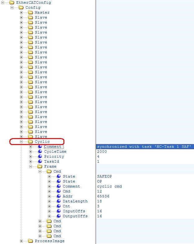
All process data synchronization modes support this configuration variant.
3.4.2. Multiple cyclic entries configuration
For more complex scenarios it is possible to configure the system using multiple cyclic entries with one or more cyclic frames for each cyclic entry.

The application has to use the EC_T_USER_JOB::eUsrJob_SendCycFramesByTaskId job call to the EC-Master to send the appropriate cyclic frame.
See also
3.4.3. Copy Information for SubDevice-to-SubDevice communication
It is possible to configure the system to copy input variables to output variables within EC-Master. The copy info declarations of the corresponding received cyclic frame are processed in emExecJob(eUsrJob_ProcessAllRxFrames).
The exchange of process data takes two communication cycles. The duration is necessary if cable redundancy is used or if the WKC of INPUT needs to be checked before changing OUTPUT.
The copy info declarations are located at /EtherCATConfig/Config/Cyclic/Frame/Cmd/CopyInfos in the ENI file.
See also
CopyInfosType in ETG.2100
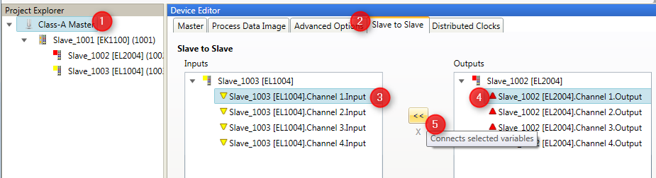
Configuration with EC-Engineer
- In the “SubDevice to SubDevice” tab of the MainDevice select Input and Output Variable and connect them:
Configuration with ET9000
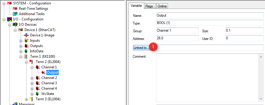
- Select “Linked to…” from the Output Variable:
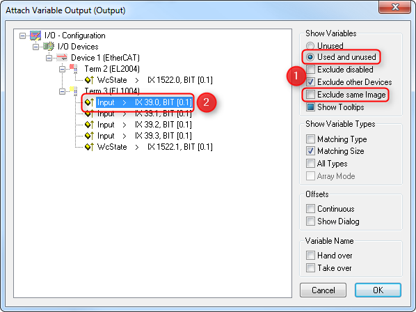
- Select Input Variable to be attached to the Output Variable:
Hint
Copy info declaration processing is independent of WKC values, but updating the INPUT source depends on successful Cyclic cmd WKC validation.
3.4.4. Swap bytes of variables according to ENI
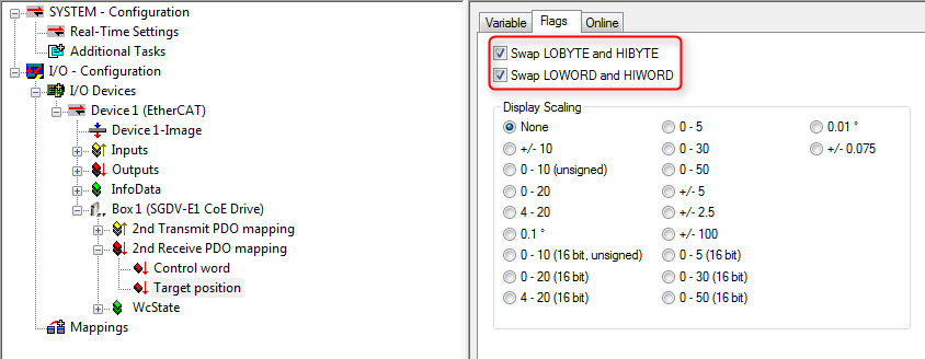
The following screenshot (ET9000) shows how to configure variables to be swapped by the EC-Master:
Hint
The EC-Master does not distinguish between WORD or BYTE swapping. Setting any PDO swap flag instructs the EC-Master to swap the PDO variable.
The swap declarations are located at DataType’s attribute SwapData of RxPdo or TxPdo, e.g. /EtherCATConfig/Config/Slave/ProcessData/RxPdo/Entry/DataType in the ENI file.